MG.20.B6.02 – VLT is a registered Danfoss trademark
VLT
®
2000 Series
76
Description of parameters
409 Terminal 01
Relay output (RELAY OUT 01)
Value:
✭ Unit ready (UNIT READY) [0]
Unit ready remote control (
UNT RDY CRLT) [1]
Enabled no warning (ENABLEDnoWR) [2]
Running (RUNNING) [3]
Running no warning (RUNNINGnoWR) [4]
Running in range no warning
(RNinRGEnoWR) [5]
Running on reference no warning
(RUN@REF noWR) [6]
Alarm (ALARM) [7]
Alarm or warning (ALARMorWARN) [8]
Current limit (CURRENT LIM) [9]
Out of frequency range (OUT FRQ RGE) [10]
Out of current range (OUT CURR RGE) [11]
Reversing (REVERSING) [12]
Description:
You can use the relay output 01 to indicate selected
status and warnings. The relay is activated when the
conditions for the selected data values are fullfilled.
When relay output 01 is not active, there is no
connection between terminal 01 and terminal 02.
The relay output is potential-free and the maximum
load is 2 A at 24 V DC or 250 V AC.
■
411 Analogue input current (ANALOG REFTYPE)
Value:
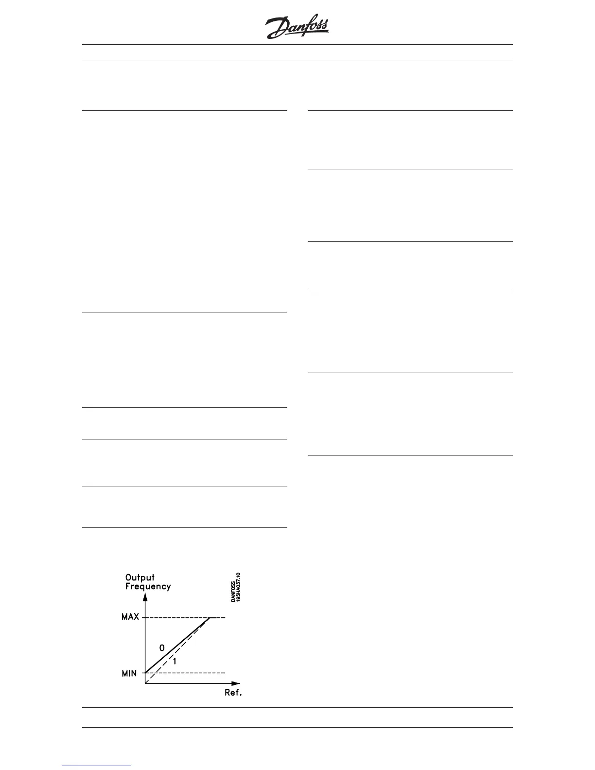
✭ Linear between min. and max. (LINEAR) [0]
Proportional with lower limit (PROP W/MIN) [1]
Function:
Is used to determine which frequency converter is to
follow an analogue reference signal.
Description:
When you select [1] the reference signal will not affect
the output frequency until it reaches a value equivalent
to the set minimum frequency (parameter 201).
412 Terminal 53
Analogue input voltage (INPUT #53)
Value:
No function (NO OPERATION) [0]
✭ 0-10 V (0-10 VDC) [1]
10-0 V (10-0 VDC) [2]
Description:
Record the polarity of analogue control signals to
inputs 53 and 60. You can choose between voltage,
current and polarity.
If you use both inputs for reference signals the total
reference signal will be a summation.
413 Terminal 60
Analogue input current (INPUT #60)
Value:
No function (NO OPERATION) [0]
✭ 0-20 mA (0-20 mA) [1]
4-20 mA (4-20 mA) [2]
20-0 mA (20-0 mA) [3]
20-4 mA (20-4 mA) [4]
Description:
If you are using a PI controller one of the inputs or the
pulse input must be used for the feedback signal.
If you are using current control, one of the inputs
must be used to set a current limit.
Naturally these choices block the same type of
reference signal.
✭ = Factory setting. Text in ( ) = Display text. The figures in [ ] are used in bus communication.
■
■
■
 Loading...