FCM 300 / FCD 300 / VLT
®
2800 / DP V1 PROFIBUS
The Profibus
Interface
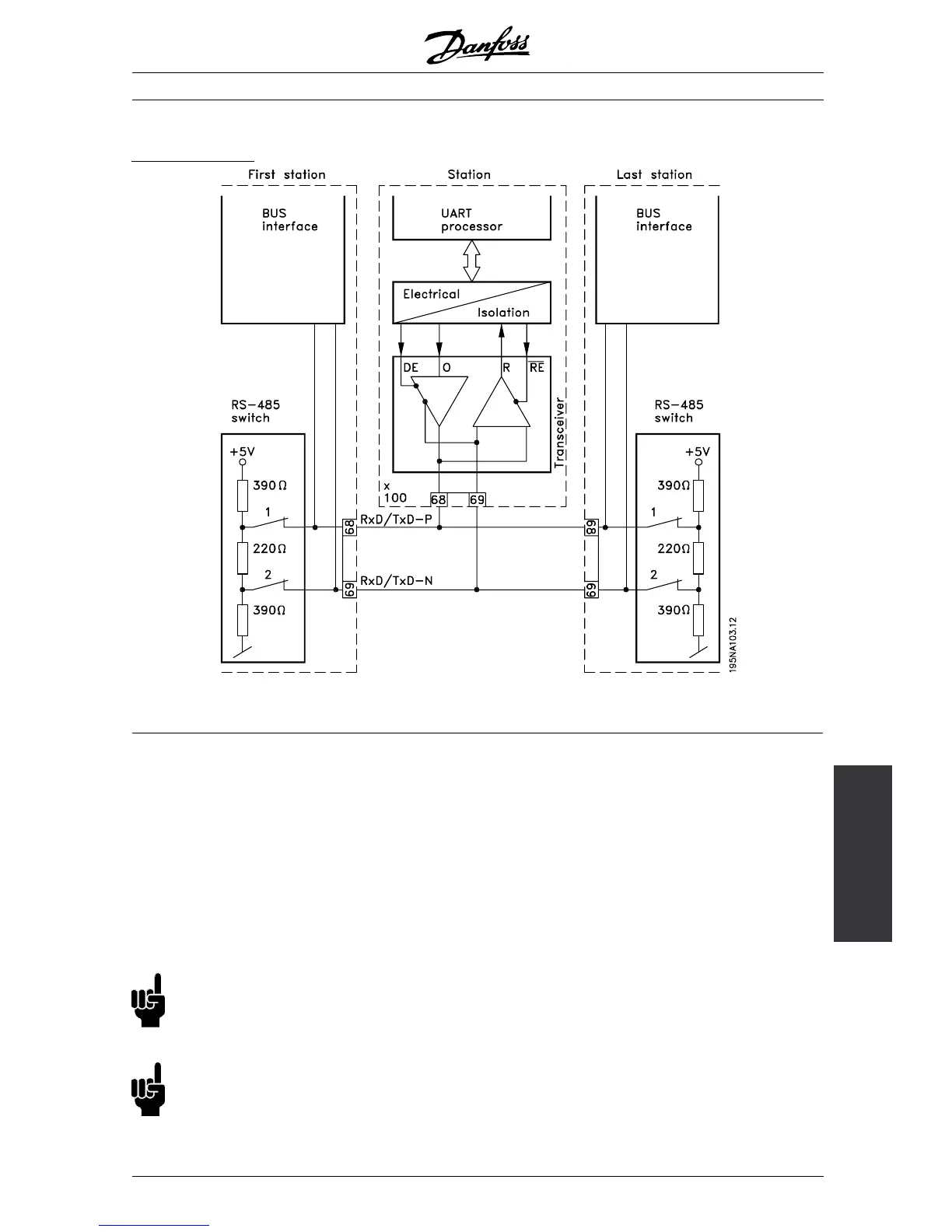
The bus ter mination
68 = RxD/TxD-P
∼ (red cable)
69 = RxD/TxD-N
∼ (green cable)
It is essential that the bus line be terminated properly.
A m is match of impedance may result in reflections
onthelinethatwillcorruptdatatransmission.
- The PROFIBUS is provided with a suitable
termination which may b e activated by the switches
of the RS485 switch block located on the bottom
of the electronics part (see drawing be low). The
switches s hould be on to term inate the b us.
- Most masters and repeaters are equipped
with their own termination.
NB!:
The switches should never be left in opposite
positions. They should either both be
ON or both be OFF!
NB!:
Is 126 or 127 selected the address is setting
via P918, refer to chapter station address.
- If an externa l termination circuit consisting of three
resistors is connec ted to the bus line a 5 V d.c.
power supply must be used, please note that this
must be galvanically isolated from the a.c. line.
MG.90.A5.02 - VLT is a registered Danfoss trademark
15
 Loading...


