2. The values are stated by the motor supplier.
3. The values are obtained by means of manual
measurements:
-
R
S
can be calculated by measuring
the resistance R
PHASE-to-PHASE
be-
tween two phase terminals. If
R
PHASE-to-PHASE
is lower than 1-2
ohm (typically motors >4-5.5 kW,
400 V), a special ohm-meter should
be used (Thomson bridge or simi-
lar). R
S
= 0.5 x R
PHASE-to-PHASE
4. The factory settings of R
S
, selected by the
adjustable frequency drive itself on the basis
of the motor nameplate data, are used.
NOTE
If the setting in parameter 102-109 is
changed, the parameters 110-118 will re-
turn to factory setting. If using special mo-
tor characteristics a change in parameter
102-109 affects parameter 422.
109 Stator reactance
(STATOR REACT.)
Value:
depends on the choice of motor
Function:
After setting motor data in parameters 102-106, a
number of adjustments of various parameters are
made automatically, including the stator reactance
X
S
. The shaft performance can be improved by fine-
tuning R
S
and X
S
, see procedure below.
Description of choice:
X
S
can be set as follows:
1. Automatic motor adaptation, where the ad-
justable frequency drive measures on the
motor to determine the value. All compensa-
tions are reset to 100%.
2. The values are stated by the motor supplier.
3. These values are obtained by means of man-
ual measurements:
- X
S
can be calculated by connect-
ing a motor to line power and meas-
uring the phase-to-phase voltage
U
L
as well as the idling current I
Ɏ
.
Alternatively, these values can be
recorded during operation in idle
running state at the rated motor fre-
quency f
M,N
, slip compensation (par.
115) = 0% and load compensation
at high speed (par. 114) = 100%.
X
S
=
U
L
3×
l
ˎ
4. The factory settings of X
S
, selected by the
adjustable frequency drive itself on the basis
of the motor nameplate data, are used.
NOTE
If the setting in parameter 102-109 is
changed, the parameters 110-118 will re-
turn to the factory setting. If using special
motor characteristics, a change in param-
eter 102-109 affects parameter 422.
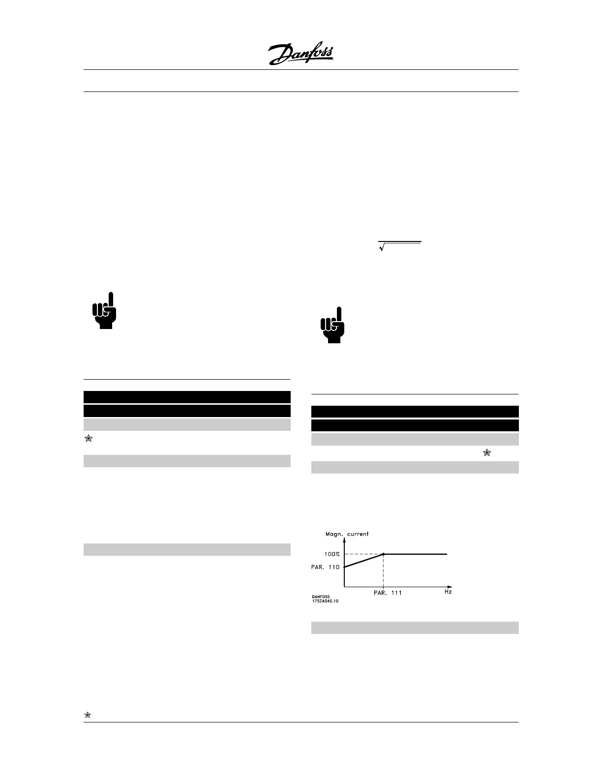
110 Motor magnetizing, 0 rpm
(MOT. MAGNETIZING)
Value:
0 - 300 %
100 %
Function:
This parameter can be used if a different thermal load
on the motor is desired when running at low speed.
This parameter is used in connection with parameter
111.
Description of choice:
Enter a value stated as a percentage of the rated mag-
netizing current.
Too low setting may lead to a reduced torque on the
motor shaft.
VLT
®
5000 Series
= factory setting, () = display text, [] = value for use in communication via serial communication port
92 MG.51.C5.22 - VLT
p
is a registered Danfoss trademark.
 Loading...


