8.1.7 Wiring Configuration: Start/Stop
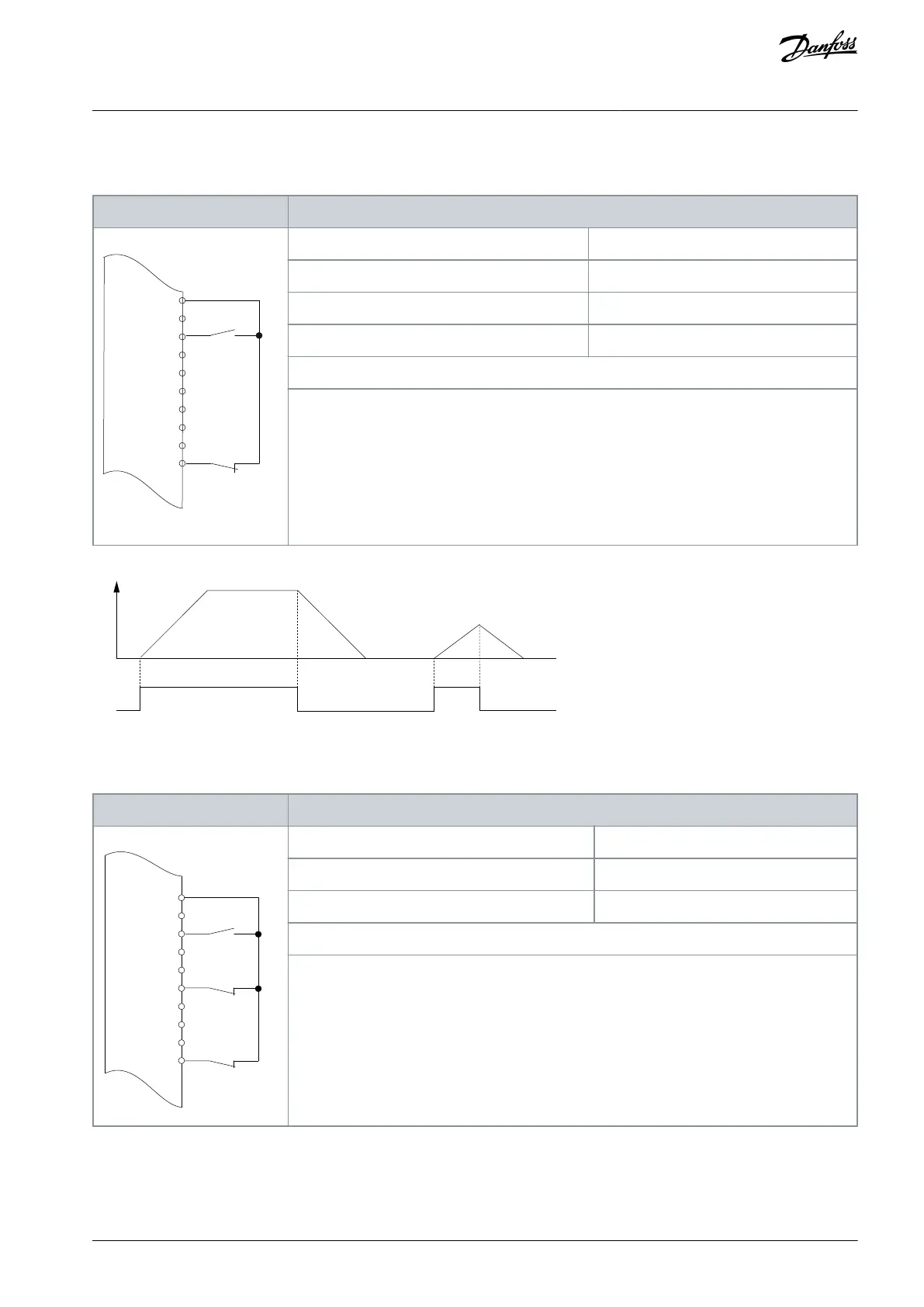
Table 86: Wiring Configuration for Start/Stop Command with Safe Torque Off Option
+24 V
D IN
D IN
D IN
COM
D IN
D IN
D IN
D IN
XD2.11
XD2.12
XD2.13
XD2.18
XD2.14
XD2.15
XD2.16
XD2.17
XD2.19
Parameter 5-10 Terminal 18 Digital Input
Parameter 5-12 Terminal 27 Digital Input
Parameter 5-19 Terminal 37 Safe Stop
Notes/comments:
If parameter 5-12 Terminal 27 Digital Input is set to [0] No operation, a jumper wire to terminal
XD2.14 is not needed.
D IN 37 is an option.
Terminal 18 in the parameter title corresponds to terminal XD2.12 in the control compartment.
Terminal 27 in the parameter title corresponds to terminal XD2.14 in the control compartment.
Terminal 37 in the parameter title corresponds to terminal XD2.19 in the control compartment.
Illustration 68: Wiring Configuration for Start/Stop Command with Safe Torque Off
Table 87: Wiring Configuration for Pulse Start/Stop
+24 V
+24 V
D IN
D IN
D IN
COM
D IN
D IN
D IN
D IN
XD2.12
XD2.13
XD2.18
XD2.14
XD2.15
XD2.16
XD2.17
XD2.19
Parameter 5-10 Terminal 18 Digital Input
Parameter 5-12 Terminal 27 Digital Input
Notes/comments:
If parameter 5-12 Terminal 27 Digital Input is set [0] No operation, a jumper wire to terminal
XD2.14 is not needed.
D IN 37 is an option.
Terminal 18 in the parameter title corresponds to terminal XD2.12 in the control compartment.
Terminal 27 in the parameter title corresponds to terminal XD2.14 in the control compartment.
AQ262139143212en-000301 / 130R0879 | 129Danfoss A/S © 2021.10
Wiring Configuration Examples
VLT® AutomationDrive FC 302
Operating Guide
 Loading...


