•
•
•
•
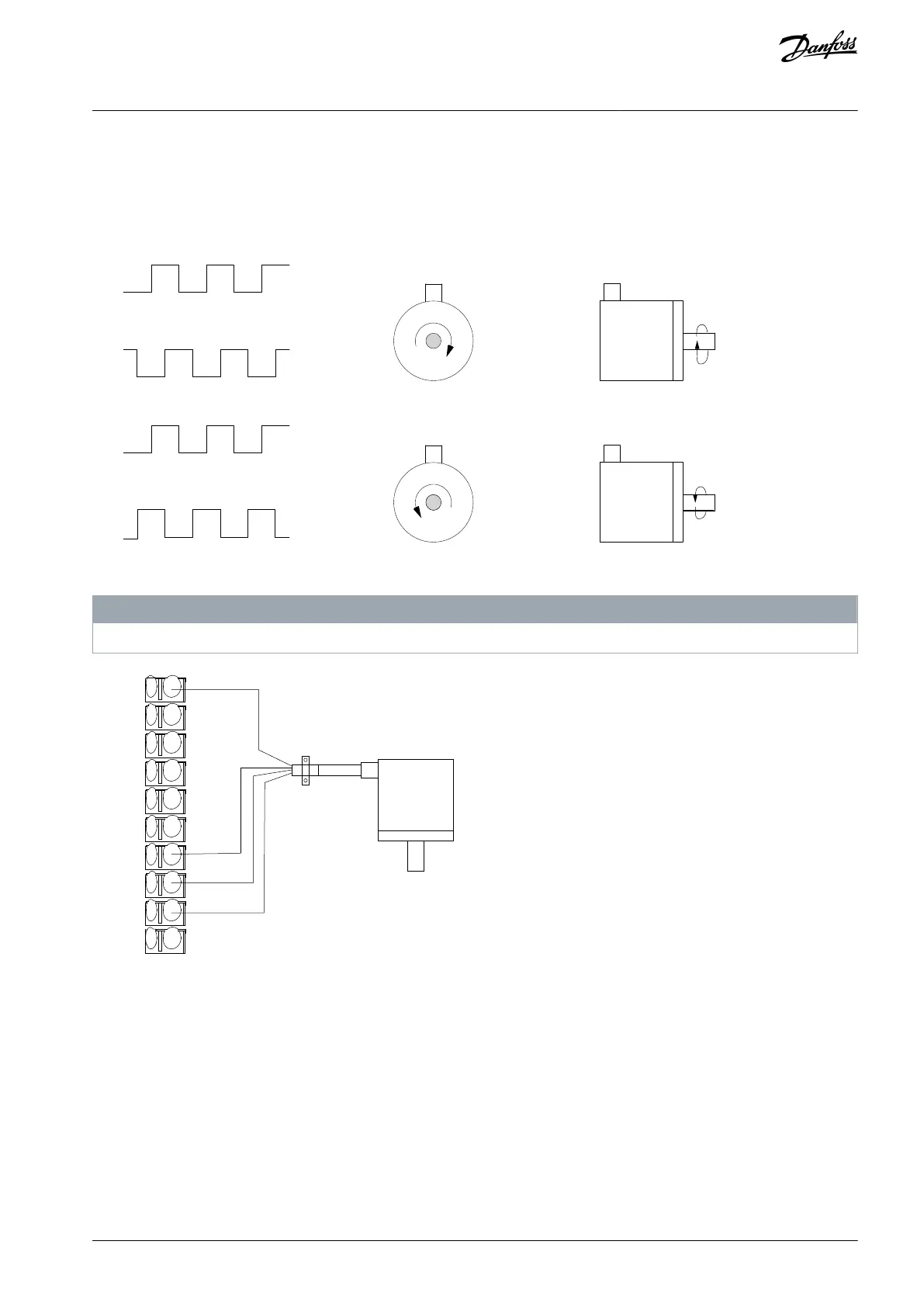
8.1.14 Wiring Configuration for the Encoder
The direction of the encoder, identified by looking into the shaft end, is determined by which order the pulses enter the drive.
Clockwise (CW) direction means channel A is 90 electrical degrees before channel B.
Counterclockwise (CCW) direction means channel B is 90 electrical degrees before A.
Illustration 71: Determining Encoder Direction
N O T I C E
Maximum cable length is 5 m (16 ft.)
e30bu095.10
+24 V DC
GND
XD2.19
XD2.18
XD2.17
XD2.16
XD2.15
XD2.14
XD2.13
XD2.12
24 V or 10–30 V encoder
A
B
Illustration 72: Wire Configuration for the Encoder
8.1.15 Wiring Configuration for Torque and Stop Limit
In applications with an external electro-mechanical brake, such as hoisting applications, it is possible to stop the drive via a standard
stop command and simultaneously activate the external electro-mechanical brake.
If a stop command is activated via terminal XD2.12 and the drive is not at the torque limit, the motor ramps down to 0 Hz. If the
drive is at the torque limit and a stop command is activated, the system activates terminal XD2.15 output (programmed to [27]
Torque limit & stop). The signal to terminal XD2.14 changes from logic 1 to logic 0 and the motor starts to coast. This process ensures
that the hoist stops even if the drive itself cannot handle the required torque, for example due to excessive overload.
Example of programming a hoisting application
To program the stop and torque limit for the above example, perform the following connections:
Connect to terminal XD2.12. Then set parameter 5-10 Terminal 18 Digital Input to 8 [Set].
Connect terminal XD2.14 to terminal XD2.15. Then set the following parameters:
AQ262139143212en-000301 / 130R0879 | 135Danfoss A/S © 2021.10
Wiring Configuration Examples
VLT® AutomationDrive FC 302
Operating Guide
 Loading...


