-
8.1.10 Wiring Configuration: Motor Thermistor
C A U T I O N
THERMISTOR INSULATION
Risk of personal injury or equipment damage.
Use only thermistors with reinforced or double insulation to meet PELV insulation requirements.
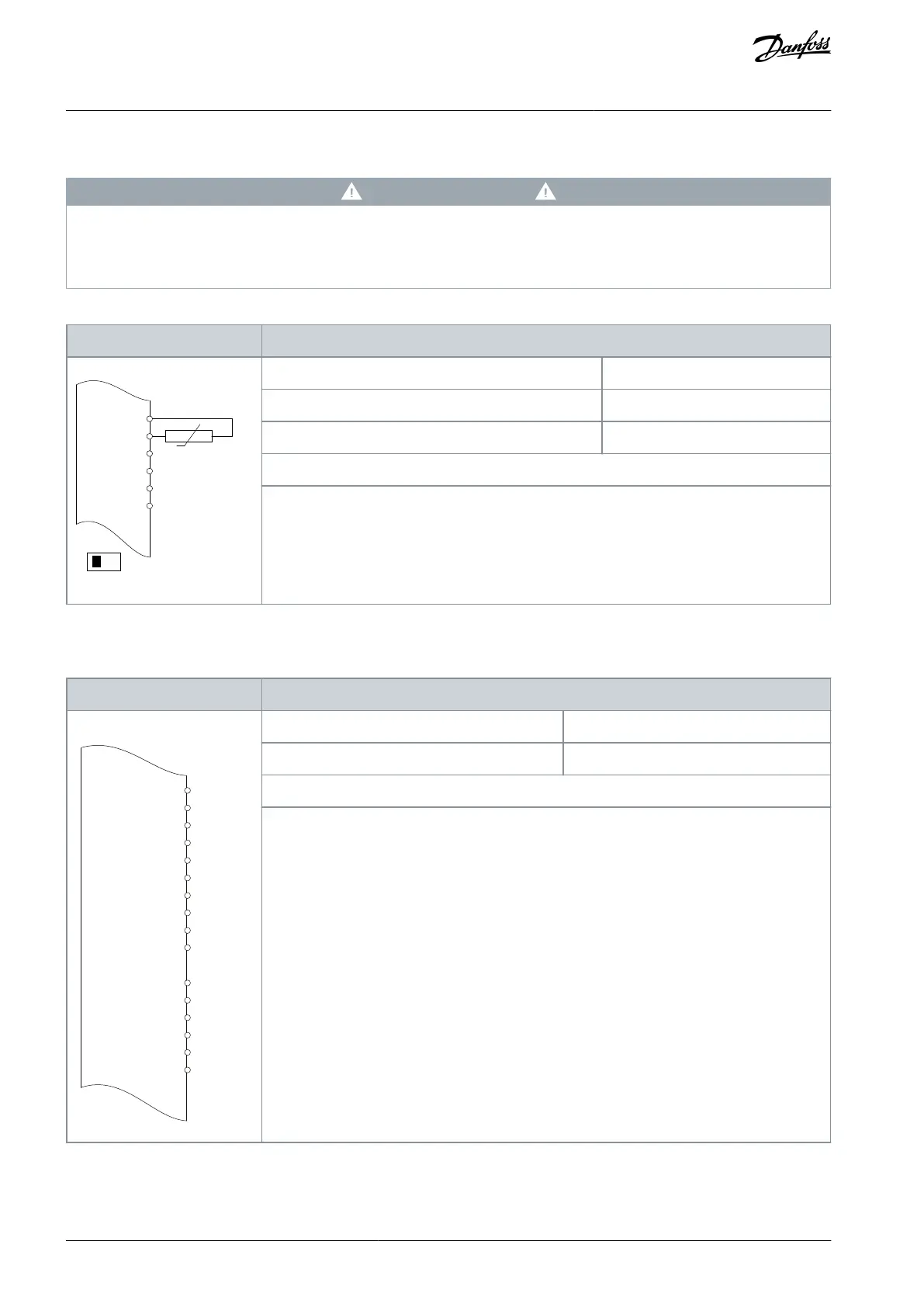
Table 91: Wiring Configuration for Motor Thermistor
Parameter 1-90 Motor Thermal Protection
Parameter 1-93 Thermistor Source
If only a warning is required, set parameter 1-90 Motor Thermal Protection to [1] Thermistor warn-
ing.
D IN 37 is an option.
Input 53 in the parameter corresponds to terminal XD2.7 in the control compartment.
8.1.11 Wiring for Regeneration
Table 92: Wiring Configuration for Regeneration
+24 V
+24 V
D IN
D IN
D IN
COM
XD2.19
XD2.6
XD2.7
XD2.8
XD2.9
XD2.5
XD2.4
e30bu091.10
Parameter 1-90 Motor Thermal Protection
To disable regeneration, decrease parameter 1-90 Motor Thermal Protection to 0%. However, if
the application uses motor brake power and regeneration is not enabled, the drive will trip.
AQ262139143212en-000301 / 130R0879132 | Danfoss A/S © 2021.10
Wiring Configuration Examples
VLT® AutomationDrive FC 302
Operating Guide
 Loading...


