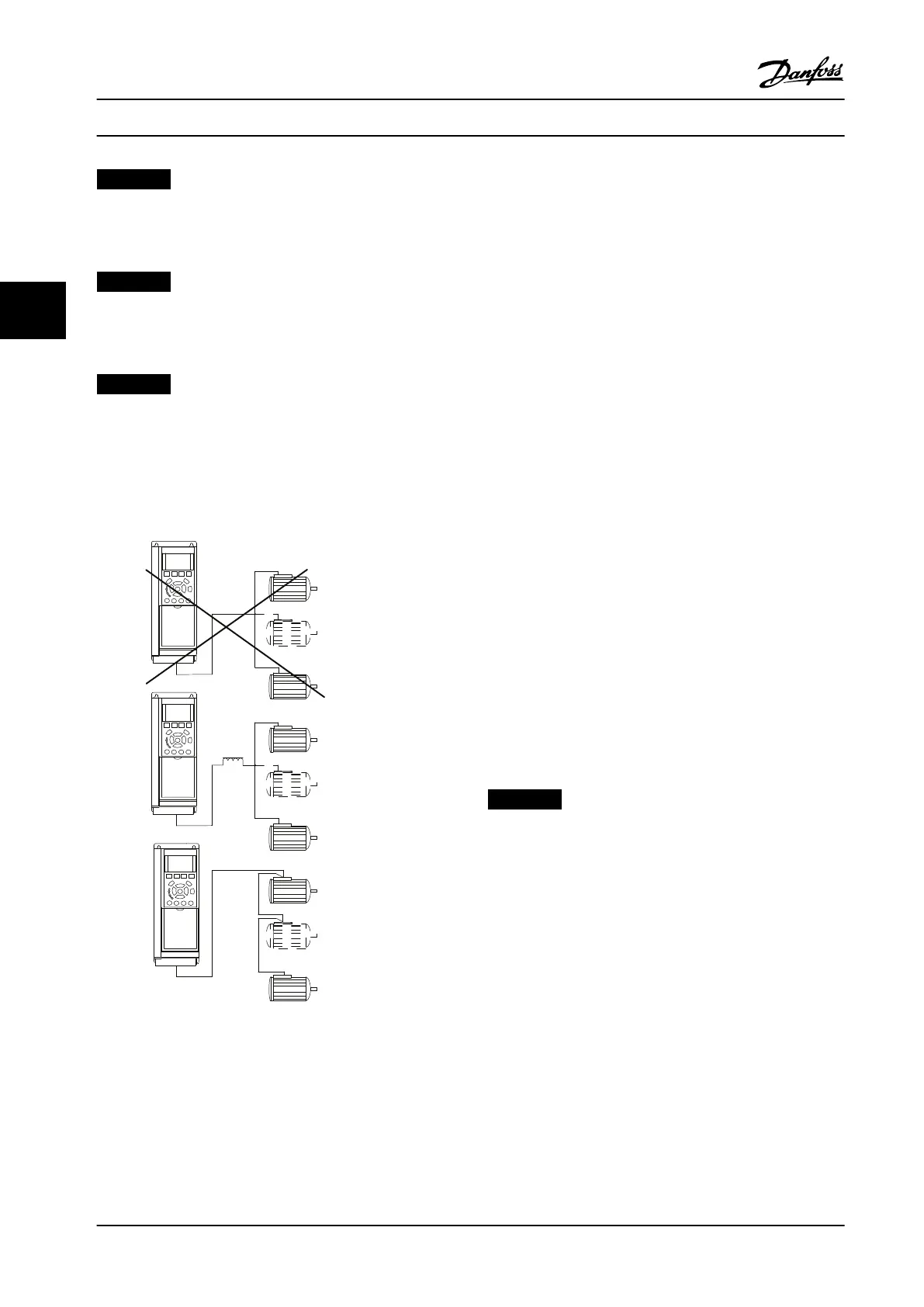
NOTICE!
Installations with cables connected in a common joint as
in Figure 4.17, is only recommended for short cable
lengths.
NOTICE!
When motors are connected in parallel,
parameter 1-29 Automatic Motor Adaptation (AMA) cannot
be used.
NOTICE!
The electronic thermal relay (ETR) of the adjustable
frequency drive cannot be used as motor protection for
the individual motor of systems with motors connected
in parallel. Provide further motor protection with
thermistors in each motor or individual thermal relays.
Circuit breakers are not suitable as protection.
Figure 4.17 Installations with Cables Connected in a Common
Joint
Problems are possible at start and at low RPM values if
motor sizes vary widely. The relatively high ohmic
resistance in the stator of small motors calls for a higher
voltage at start and at low RPM values.
4.9.4 Motor Thermal Protection
The electronic thermal relay in the adjustable frequency
drive has received UL-approval for single motor protection,
when parameter 1-90 Motor Thermal Protection is set for
ETR Trip and parameter 1-24 Motor Current is set to the
rated motor current (see motor nameplate).
For thermal motor protection, it is also possible to use the
MCB 112 PTC thermistor card option. This card provides
ATEX certication to protect motors in explosion hazardous
areas, Zone 1/21 and Zone 2/22. When
parameter 1-90 Motor Thermal Protection is set to [20] ATEX
ETR and MCB 112 are combined. It is possible to control an
Ex-e motor in explosion hazardous areas. Consult the
programming guide for details on how to set up the
adjustable frequency drive for safe operation of Ex-e
motors.
4.9.5 Voltage/Current Input Selection
(Switches)
The analog mains terminals 53 and 54 allow setting of
input signal to voltage (0–10 V) or current (0/4–20 mA).
See Figure 4.13 and for the location of the control terminals
within the low harmonic drive.
Default parameter settings:
•
Terminal 53: Speed reference signal in open loop
(see parameter 16-61 Terminal 53 Switch Setting).
•
Terminal 54: Feedback signal in closed loop (see
parameter 16-63 Terminal 54 Switch Setting).
NOTICE!
REMOVE POWER
Remove power to the low harmonic drive before
changing switch positions.
1. Remove the LCP (see Figure 4.18).
2. Remove any optional equipment covering the
switches.
3. Set switches A53 and A54 to select the signal
type. U selects voltage, I selects current.
Electrical Installation
VLT
®
AutomationDrive FC 302 Low Harmonic Drive
132–630 kW
48 Danfoss A/S © Rev. 04/2015 All rights reserved. MG37A322
44
 Loading...


