5.4.3 Commissioning via [Main Menu]
Recommended parameter settings are intended for start-
up and check-out purposes. Application settings may vary.
Enter data with power ON, but before operating the
adjustable frequency drive.
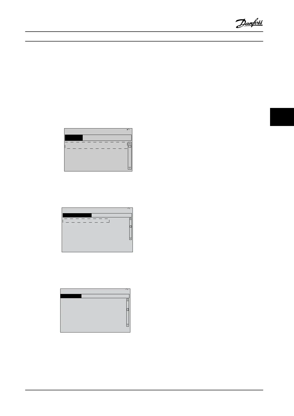
1. Press [Main Menu] on the LCP.
2. Press the navigation keys to scroll to parameter
group 0-** Operation/Display and press [OK].
130BP066.10
1107 RPM
0 - ** Operation/Display
1 - ** Load/Motor
2 - ** Brakes
3 - ** Reference / Ramps
3.84 A 1 (1)
Main Menu
Figure 5.2 Main Menu
3. Press the navigation keys to scroll to parameter
group 0-0* Basic Settings and press [OK].
0-
**
Operation / Display
0.0%
0-0
*
Basic Settings
0-1
*
Set-up Operations
0-2
*
LCP Display
0-3
*
LCP Custom Readout
0.00A 1(1)
130BP087.10
Figure 5.3 Operation/Display
4. Press the navigation keys to scroll to
parameter 0-03 Regional Settings and press [OK].
0-0
*
Basic Settings
0.0%
0-03 Regional Settings
[0] International
0.00A 1(1)
130BP088.10
Figure 5.4 Basic Settings
5. Press the navigation keys to select [0] Interna-
tional or [1] North America as appropriate and
press [OK]. (This changes the default settings for
a number of basic parameters).
6. Press [Main Menu] on the LCP.
7. Press the navigation keys to scroll to
parameter 0-01 Language.
8. Select the language and press [OK].
9. If a jumper wire is in place between control
terminals 12 and 27, leave
parameter 5-12 Terminal 27 Digital Input at factory
default. Otherwise, select No Operation in
parameter 5-12 Terminal 27 Digital Input. For
adjustable frequency drives with an optional
bypass, no jumper wire is required between
control terminals 12 and 27.
10. Make the application-specic settings in the
following parameters:
10a Parameter 3-02 Minimum Reference.
10b Parameter 3-03 Maximum Reference.
10c Parameter 3-41 Ramp 1 Ramp-up Time.
10d Parameter 3-42 Ramp 1 Ramp-down Time.
10e Parameter 3-13 Reference Site. Linked to
Hand/Auto Local Remote.
5.4.4 Asynchronous Motor Set-up
Enter the following motor data. The information can be
found on the motor nameplate.
1. Parameter 1-20 Motor Power [kW] or
parameter 1-21 Motor Power [HP].
2. Parameter 1-22 Motor Voltage.
3. Parameter 1-23 Motor Frequency.
4. Parameter 1-24 Motor Current.
5. Parameter 1-25 Motor Nominal Speed.
When running in
ux mode, or for optimum performance
in VVC
+
mode, extra motor data is required to set up the
following parameters. The data can be found in the motor
datasheet (this data is typically not available on the motor
nameplate). Run a complete AMA using
parameter 1-29 Automatic Motor Adaptation (AMA) [1]
Enable Complete AMA or enter the parameters manually.
Parameter 1-36 Iron Loss Resistance (Rfe) is always entered
manually.
1. Parameter 1-30 Stator Resistance (Rs).
2. Parameter 1-31 Rotor Resistance (Rr).
3. Parameter 1-33 Stator Leakage Reactance (X1).
Start-up and Functional Tes... Installation Manual
MG37A322 Danfoss A/S © Rev. 04/2015 All rights reserved. 57
5 5
 Loading...


