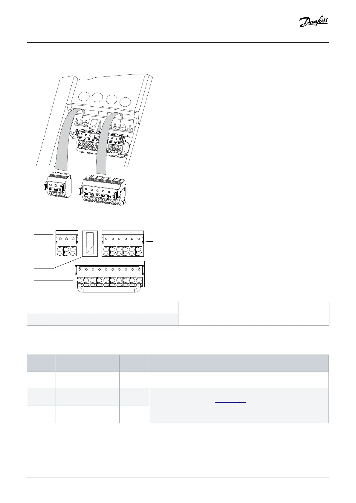
5.11.3 Control Terminal Types
Illustration 32: Control Terminal Locations
12 13 18 19 27 29 32 33 20 37
39
696861
42 50 53 54 55
e30bf145.11
1
2
4
3
1 Serial communication terminals
3 Analog input/output terminals
2 Digital input/output terminals
Illustration 33: Terminal Numbers Located on the Connectors
Table 10: Serial Communication Terminals
Terminal Parameter Default
Setting
Description
61 – – Integrated RC-filter for cable shield. ONLY for connecting the shield if EMC
problems exist.
68 Parameter group 8-3* FC
Port Settings
– RS485 interface. A switch (BUS TER.) is provided on the control card for bus
termination resistance. See illustration 38.
69 Parameter group 8-3* FC
Port Settings
–
Electrical Installation
Operating Guide | VLT® Refrigeration Drive FC 103
AQ275652766279en-000101 / 130R0707| 57
Danfoss A/S © 2020.01
 Loading...


