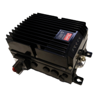
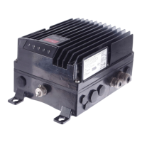
VLT
®
FCD Series
outputs can be programmed to give a warning signal
via terminal 46 and via the relay output.
Description of choice:
The output frequency’s upper signal limit f
HIGH
must
be programmed within the frequency converter’s
normal operating range. See drawing at parameter
223 Warning: Low current, I
LOW
.
227 Warning: Low feedback, FB
LOW
(WARN.FEEDB. LOW)
Value:
-100,000.000 - par. 228 Warn.:FB
HIGH
✭ -4000.000
Function:
If the feedback signal falls below the preset
limit FB
LOW
,awarningisgiven.
Parameters 223-228 Wa rning funct ions are out of
function during ramp-up after a start command and
after a stop command or during stop. The warning
functions are activated when the output frequency has
reached the resulting reference.The signal outputs can
be programmed to give a warning signal via terminal 46
and via the relay output.The unit for feedback in Closed
loop is programmed in parameter 416 Process units.
Description of choice:
Set the required value within the feedback range
(parameter 414 Minimum feedback, FB
MIN
and
415 Maximum feedback, FB
MAX
).
228 Warning: High feedback, FB
HIGH
(WARN.FEEDB HIGH)
Value:
Par. 227 Warn.: FB
LOW
- 100,000.000
✭ 4000.000
Function:
If the feedback signal gets above the preset
limit FB
HIGH
,awarningisgiven.
Parameters 223-228 Wa rning funct ions are out of
function during ramp-up after a start command
and after a stop command or during stop. The
warning functions are activated when the output
frequency has reached the resulting reference.
The signal outputs can be programmed to give a
warning signal via terminal 46 and via the relay
output. The unit for feedback in Closed loop is
programmed in parameter 416 Process units.
Description of choice:
Set the required value within the feedback range
(parameter 414 Minimum feedback, FB
MIN
and
415 Maximum feedback, FB
MAX
).
229 Frequence bypass, bandwidth
(FREQ BYPASS B.W.)
Value:
0 (OFF) - 100 Hz
✭ 0Hz
Function:
Some systems call for some output frequencies
to be avoided because of mechanical resonance
problems in the system. In parameters 230-231
Frequency bypass these output frequencies can be
programmed. In this parameter a bandwidth can be
defined on either side of these frequencies.
Description of choice:
The frequency set in this parameter will be centered
around parameters 230 Frequency bypass 1
and 231 Frequency bypass 2.
230 Frequency bypass 1 (FREQ. BYPASS 1)
231 Frequency bypass 2 (FREQ. BYPASS 2)
Value:
0 - 1000 Hz
✭ 0.0 Hz
Function:
Some systems call for some output frequencies
to be avoided because of mechanical resonance
problems in the system.
Description of choice:
Enter the frequencies to be avoided. See also
parameter 229 Frequency bypass, bandwidth.
✭ = factory setting. () = display text [] = value for use in communication via serial communication port
MG.04.B7.02 - VLT is a registered Danfoss trademark
56
 Loading...


