VLT
®
FCD Series
Bit 04, Not used:
Bit 04 is not used in the status word.
B
it 05, Not used:
Bit 05 is not used in the status word.
B
it 06, Trip lock:
Bit 06 = ’0’ means that the frequency converter
is not trip locked.
Bit 06 = ’1’ means that the frequency converter
is trip locked and it cannot be reset before the
mains supply has been removed. The trip can be
reset either with 24 V external control back up or
after the power is connected again.
B
it 07, No warning/warning:
Bit 07 = ’0’ means that there are no warnings.
Bit 07 = ’1’ means that a warning has occurred.
B
it 08, Speed≠ ref/speed = ref.:
Bit 08 = ’0’ means that the motor is running, but that
the present speed is different from the preset speed
reference. It might, for example, be the case while the
speed is being ramped up/down during start/stop.
Bit 08 = ’1’ means that the motor’spresentspeed
is the same as the preset speed reference.
B
it 09, Local operation/serial communication control:
Bit 09 = ’0’ means that [STOP/RESET] is activated on
the control unit, or that Local control in parameter
002 Local/remote operat ion is selected. It is
not possible to control the frequency converter
via serial communication.
Bit 09 = ’1’ means that it is possible to control the
frequency converter via serial communication.
B
it 10, Outside frequency range:
Bit 10 = ’0’, if the output frequency has reached
the value in parameter 201 Output frequency
low limit or parameter 202 Output frequency
high lim it. Bit 10 = "1" means that the output
frequency is within the defined limits.
B
it 11, Running/not running:
Bit 11 = ’0’ means that the motor is not running.
Bit 11 = ’1’ means that the frequency converter
has a start signal or that the output frequency
is greater than 0 Hz.
B
it 13, Voltage warning high/low:
Bit 13 = ’0’ means that there are no voltage warnings.
Bit 13 = ’1’ means that the DC voltage in the frequency
converter’s intermediate circuit is too low or too high.
B
it 14, Current limit:
Bit 14 = ’0’ means that the output current is less than
the value in parameter 221 Current Limit I
LIM
.
Bit 14 = ’1’ means that the output current is
greater than the value in parameter 221 C urrent
LimitI
LIM
and that the frequency converter will
trip after a set period of time.
B
it 15, Thermal warning:
Bit 15 = ’0’ means that there is no thermal warning.
Bit 15 = ’1’ means that the temperature limit has been
exceeded in either the motor, frequency converter or
from a thermistor that is connected to a digital input.
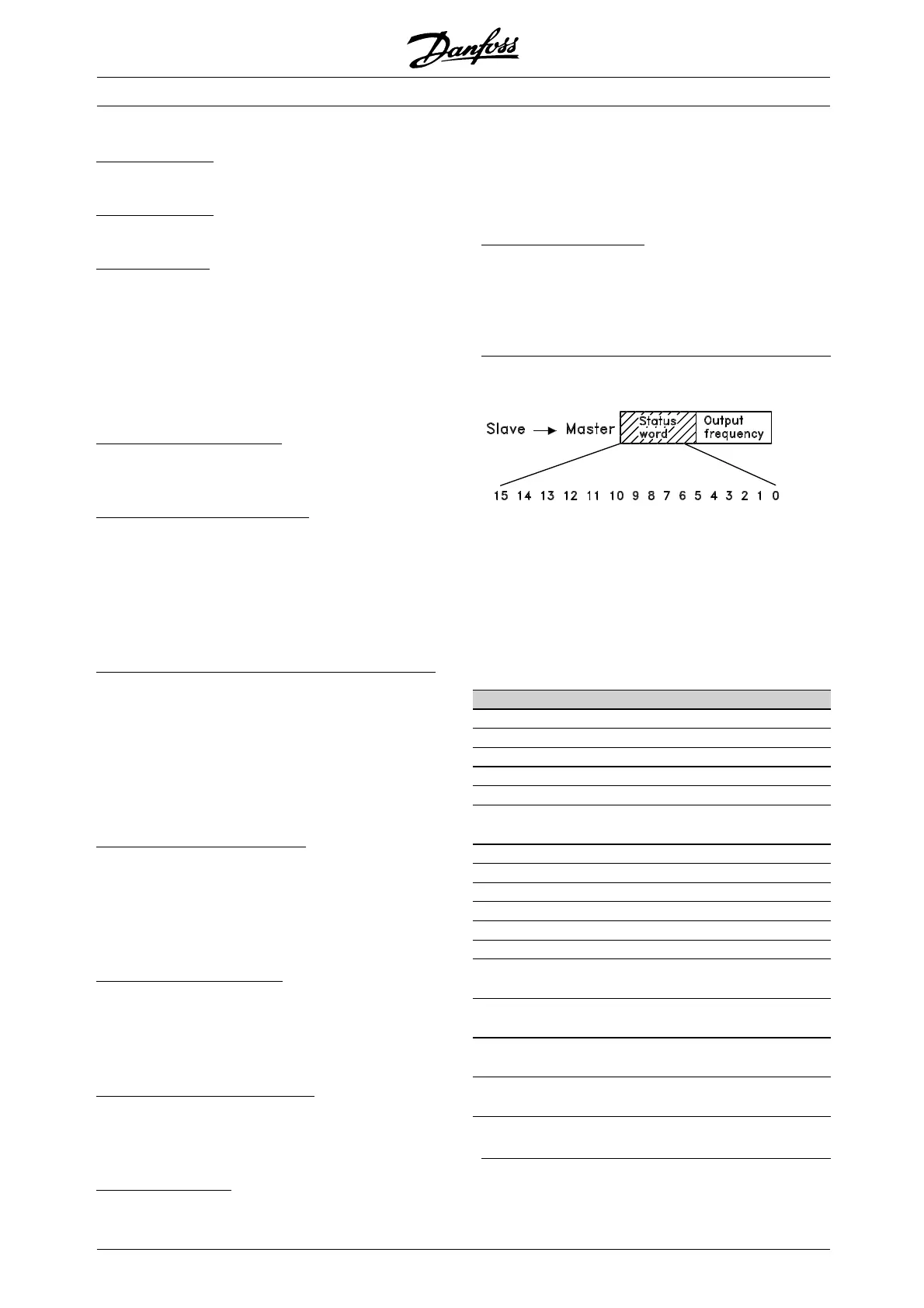
■ Fast I/O FC-profile
The Fast I/O FC-profile can be used to monitor the
digital inputs just by reading the status word. The
input status in the status word reflects the actual
input state (High or Low) regardless of the selected
digital input function. The fast I/O profile(s) will
only be available in drives fitted with Profibus. The
response time from input changes until it is available
on the Profibus is approximately 10 mS.
Bit Bit =0 Bit =1
00 Control ready
01 Drive ready
02 Coasting stop
03 No trip Trip
04 Not used
05 Digital input 27 0: Input LOW/
1: Input HIGH
06 Trip lock
07 No warning Warning
08 Speed ≠ ref. Speed = ref.
09 Local control Ser. communication
10 Outside frequency range Frequency limit OK
11 Motor OK
12 Digital input 18 0: Input LOW/
1: Input HIGH
13 Digital input 19 0: Input LOW/
1: Input HIGH
14 Digital input 29 0: Input LOW/
1: Input HIGH
15 Digital input 33 0: Input LOW/
1: Input HIGH
MG.04.B7.02 - VLT is a registered Danfoss trademark
84
 Loading...


