Bit 06, Ramp stop/start:
Bit 06 = ‘0’ causes a stop, in which the motor speed is ramped down to
stop via the selected
ramp down
parameter. Bit 06 = ‘1’ permits the fre-
quency converter to start the motor, if the other starting conditions have
been fulfilled.
NB!
In par. 8-53
Start Select
Start select a selection is made
to define how Bit 06 Ramp stop/start gates with the
corresponding function on a digital input.
Bit 07, Reset:
Bit 07 = ‘0’ no reset. Bit 07 = ‘1’ resets a trip. Reset is activated on the
leading edge of the signal, i.e. when changing from logic ‘0’ to logic ‘1’.
Bit 08, Jog:
Bit 08 = ‘1’ causes the output frequency to be determined by
par. 3-19
Jog Speed [RPM]
.
Bit 09, Selection of ramp 1/2:
Bit 09 = ‘0’ means that ramp 1 is active (par. 3-40
Ramp 1 Type
to
par. 3-47
Ramp 1 S-ramp Ratio at Decel. Start
). Bit 09 = ‘1’ means that
ramp 2 (par. 3-50
Ramp 2 Type
to par. 3-57
Ramp 2 S-ramp Ratio at
Decel. Start
) is active.
Bit 10, Data not valid/Data valid:
This bit tells the frequency converter whether the control word is to be
used or ignored. Bit 10 = ‘0’ causes the control word to be ignored, Bit
10 = ‘1’ causes the control word to be used. The control word is always
contained in the telegram, regardless of which type of telegram is used,
so this function is useful for ‘turning off’ the control word when not re-
quired for updating or reading parameters.
Bit 11, Relay 01:
Bit 11 = ‘0’ Relay not activated. Bit 11 = ‘1’ Relay 01 activated, provided
Control word bit 11
has been chosen in par. 5-40
Function Relay
.
Bit 12, Relay 02:
Bit 12 = ‘0’ Relay 02 has not been activated. Bit 12 = ‘1’ Relay 02 has
been activated, provided
Control word bit 12
has been chosen in
par. 5-40
Function Relay
.
Bit 13/14, Selection of set-up:
Bits 13 and 14 are used to select one of four menu set-ups according to
the following table:
Set-up
Bit 14 Bit 13
1 0 0
20 1
3 1 0
41 1
The function is only possible when
Multi-Set-ups
is selected in
par. 0-10
Active Set-up
.
NB!
In par. 8-55
Set-up Select
a selection is made to define
how Bit 13/14 gates with the corresponding function
on the digital inputs.
Bit 15 Reverse:
Bit 15 = ‘0’ causes no reversing. Bit 15 = ‘1’ causes reversing. Note: In
the factory setting reversing is set to
digital
in par.8-54
Reversing Se-
lect
. Bit 15 causes reversing only when
Ser. communication
,
Logic AND
or
Logic OR
is selected.
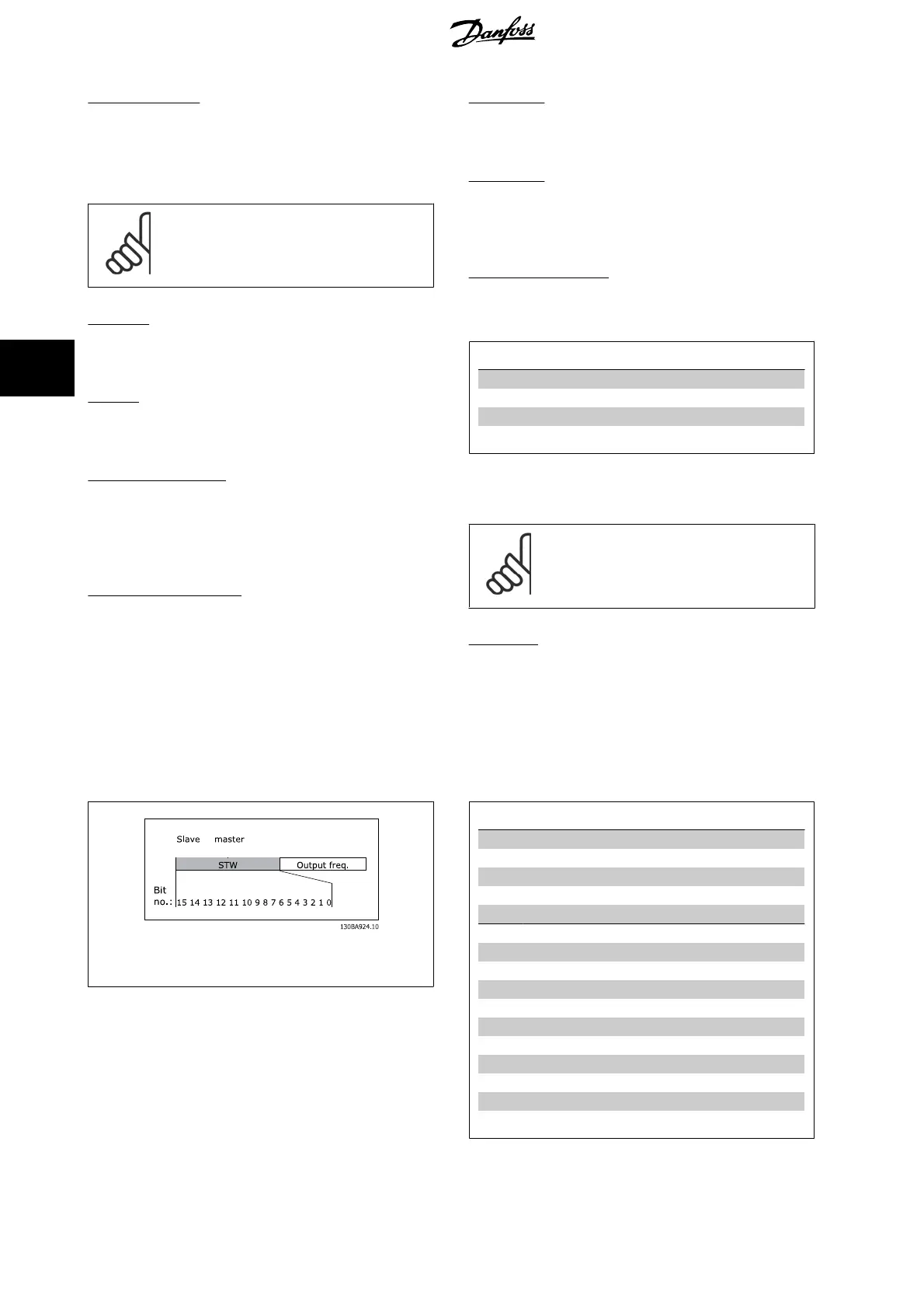
5.2.2 Status Word according to FC ProfileDrive Profile (STW)
→
Illustration 5.2: (par.8-10
Control Word Profile
)
Bit Bit value = 0 Bit value = 1
00 Control not ready Control ready
01 Drive not ready Drive ready
02 Coasting Enable
03 No error Trip
04 No error Error (no trip)
05 Reserved -
06 No error Trip lock
07 No warning Warning
08 Speed ≠ reference Speed = reference
09 Local operation Bus control
10 Out of frequency limit Frequency limit ok
11 No operation In operation
12 Drive ok Stopped, auto start
13 Voltage ok Voltage exceeded
14 Torque ok Torque exceeded
15 Thermal ok Thermal exceeded
5 How to Control MCA 121 EtherNet/IP
26
MG.90.J2.02 - VLT
®
is a registered Danfoss trademark
5

 Loading...