5.6 Danfoss FC Control Profile
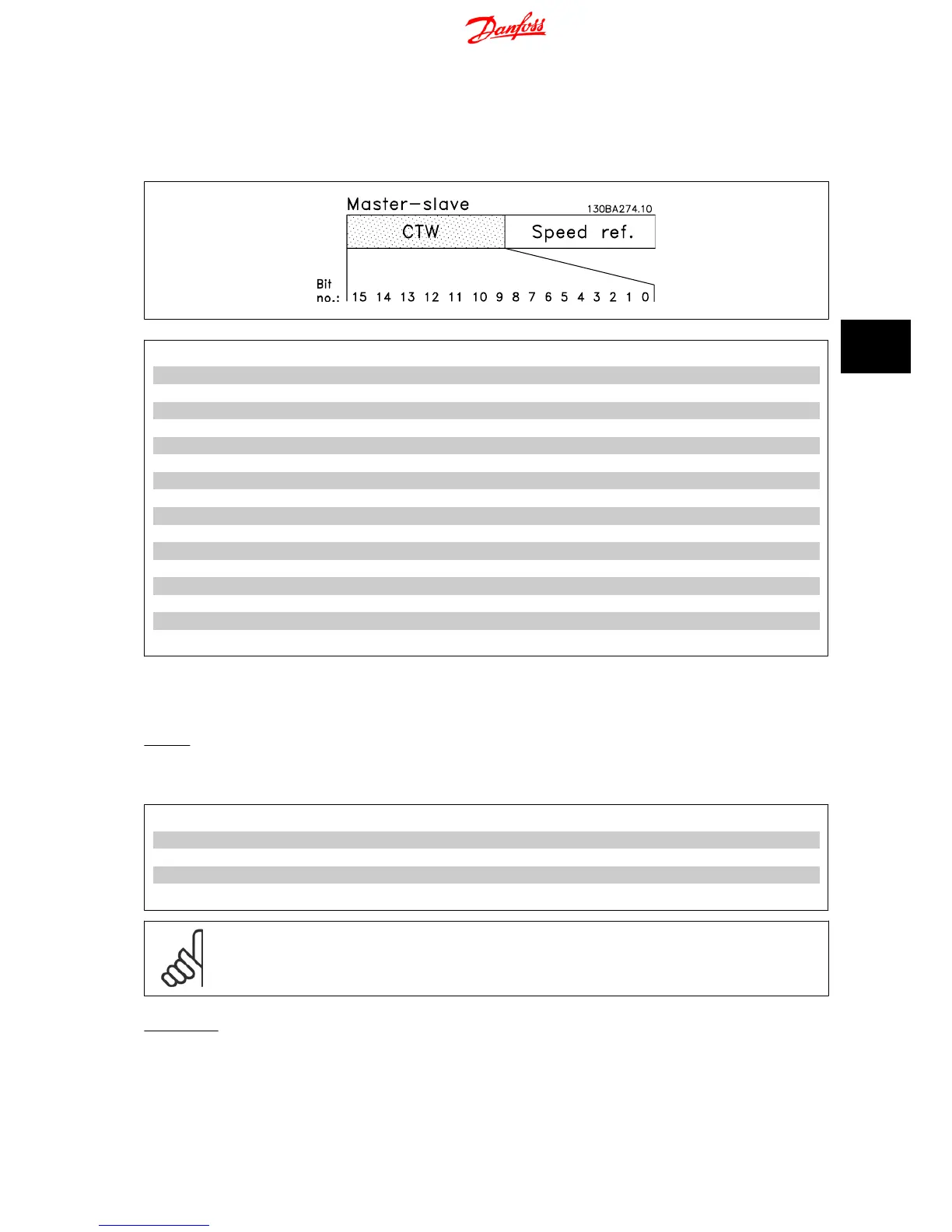
5.6.1 Control Word According to FC Profile
Bit Bit value = 0 Bit value = 1
00 Preset reference select - lsb Preset reference select - lsb
01 Preset reference select - msb Preset reference select - msb
02 DC brake Ramp
03 Coasting No coasting
04 Quick stop Ramp
05 Freeze output No freeze output
06 Ramp stop Start
07 No function Reset
08 No function Jog
09 Ramp 1 Ramp 2
10 Data invalid Data valid
11 No function Relay 01 active
12 No function No function
13 Setup 1 Setup 2
14 No function No function
15 No function Reverse
5.6.2 Explanation of the Control Bits
Bits 00/01
Bits 00 and 01 are used to choose between the four reference values, which are pre-programmed in par. 3-10
Preset Reference
according to the following
table:
Programmed ref. value Parameter Bit 01 Bit 02
1 3-10 [0] 0 0
23-10 [1]0 1
3 3-10 [2] 1 0
43-10 [3]1 1
NB!
In par. 8-56
Preset reference
a selection is made to define how Bit 00/01 gates with the corresponding function on the digital inputs.
Bit 02, DC brake:
Bit 02 = “0” leads to DC braking and stop. Braking current and duration are set in par. 2-01
DC Brake current
and 2-02
Braking time
.
Bit 02 = “1” leads to ramping.
VLT
®
Micro Drive FC 51 Operating Instructions 5 Modbus RTU
MG.02.A4.02 - VLT
®
is a registered Danfoss trademark
35
5

 Loading...


