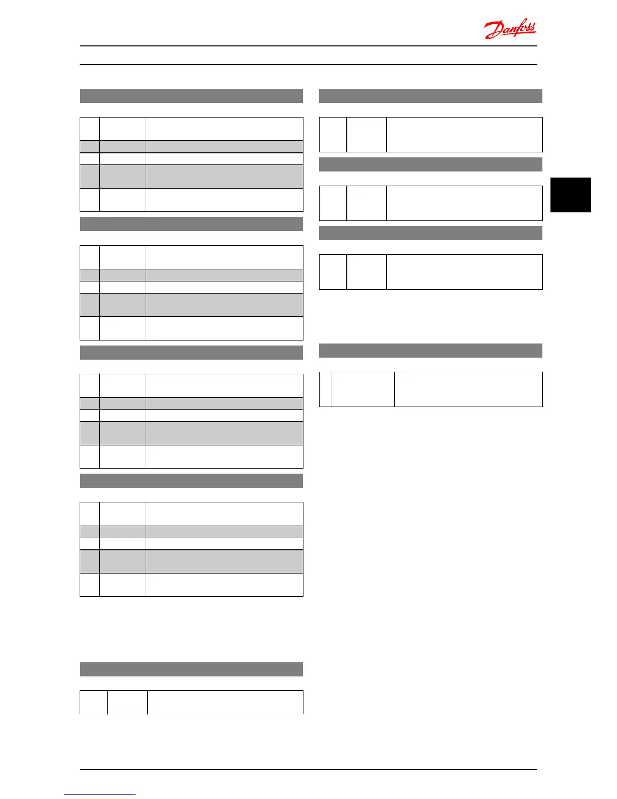
8-53 Start Select
Option: Function:
Select control of start function via digital
input and/or bus.
[0] Digital Input Activation via a digital input.
[1] Bus Activation via serial communication port.
[2] LogicAnd Activation via serial communication port and
a digital input.
[3] * LogicOr Activation via serial communication port or a
digital input.
8-54 Reversing Select
Option: Function:
Select control of reversing function via digital
input and/or bus.
[0] Digital Input Activation via a digital input.
[1] Bus Activation via serial communication port.
[2] LogicAnd Activation via serial communication port and
a digital input.
[3] * LogicOr Activation via serial communication port or a
digital input.
8-55 Set-up Select
Option: Function:
Select control of set-up selection via digital
input and/or bus.
[0] Digital Input Activation via a digital input.
[1] Bus Activation via serial communication port.
[2] LogicAnd Activation via serial communication port and
a digital input.
[3] * LogicOr Activation via serial communication port or a
digital input.
8-56 Preset Reference Select
Option: Function:
Select control of Preset Reference selection
via digital input and/or bus.
[0] Digital Input Activation via a digital input.
[1] Bus Activation via serial communication port.
[2] LogicAnd Activation via serial communication port and
a digital input.
[3] * LogicOr Activation via serial communication port or a
digital input.
4.9.6 8-8* Bus communication diagnostics
These parameters are used for monitoring the Bus
communication via the Port.
8-80 Bus Message Count
Range: Function:
0 N/A* [0-0 N/A] This parameter shows the number of valid
telegrams detected on the bus.
8-81 Bus Error Count
Range: Function:
0 N/A* [0-0 N/A] This parameter shows the number of
telegrams with faults (e.g. CRC fault),
detected on the bus.
8-82 Slave Messages Rcvd
Range: Function:
0 N/A* [0-0 N/A] This parameter shows the number of valid
telegrams addressed to the slave, sent by the
frequency converter.
8-83 Slave Error Count
Range: Function:
0 N/A* [0-0 N/A] This parameter shows the number of error
telegrams, which could be executed by the
frequency converter.
4.9.7 8-9* Bus Feedback
Parameter for configuring bus feedback.
8-94 Bus Feedback 1
Range: Function:
0* [0x8000-0x7FFF] Bus feedback is delivered via FC or
Modbus by writing the feedback value into
this parameter.
Parameter Descriptions
VLT
®
Micro Drive FC 51 Programming Guide
MG02C602 - VLT
®
is a registered Danfoss trademark 39
4 4
 Loading...


