1.3.5 Connecting to Line Power and Motor
The adjustable frequency drive is designed to operate all
standard three-phased asynchronous motors.
The adjustable frequency drive is designed to accept line
power/motor cables with a maximum cross-section of
0.006 in
2
[4 mm
2
]/10 AWG (M1, M2 and M3) and maximum
cross-section 0.0248 in
2
[16 mm
2
]/6 AWG (M4 and M5).
•
Use a shielded/armored motor cable to comply
with EMC emission specifications, and connect
this cable to both the decoupling plate and the
motor metal.
•
Keep motor cable as short as possible to reduce
the noise level and leakage currents.
•
For further details on mounting of the
decoupling plate, see Instruction MI02B.
•
Also see EMC-Compatible Installation in Design
Guide MG02K.
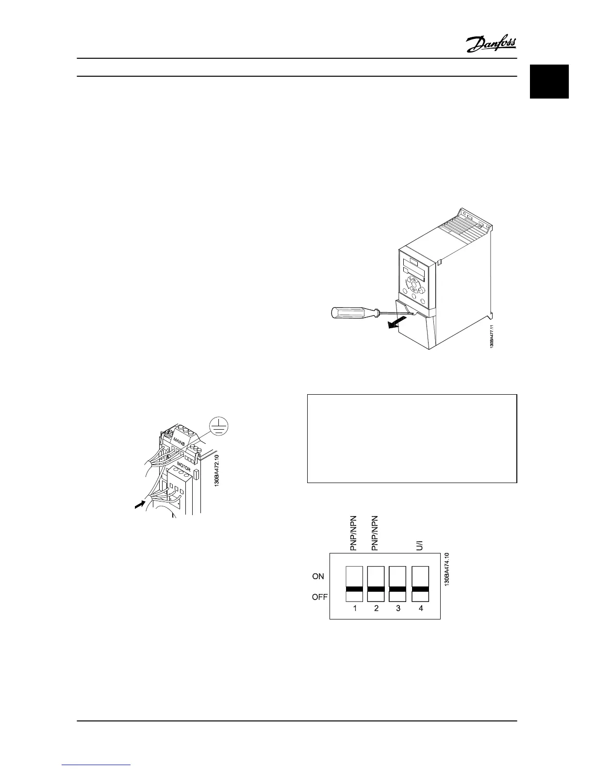
1. Mount the ground wires to the ground terminal.
2. Connect the motor to terminals U, V and W.
3. Mount line power supply to terminals L1/L, L2
and
L3/N (3-phase) or L1/L and L3/N (single-phase)
and tighten.
Figure 1.2 Mounting of Ground Cable, Line Power and Motor
Wires
1.3.6
Control Terminals
All control cable terminals are located underneath the
terminal cover in front of the adjustable frequency drive.
Remove the terminal cover using a screwdriver.
NOTE!
See back of terminal cover for outlines of control terminals
and switches.
NOTE!
Do not operate switches with power on the adjustable
frequency drive.
6-19 Terminal 53 Mode must be set according to Switch 4
position.
Figure 1.3 Removing Terminal Cover
Switch 1: *OFF=PNP terminals 29
ON=NPN terminals 29
Switch 2: *OFF=PNP terminal 18, 19, 27 and 33
ON=NPN terminal 18, 19, 27 and 33
Switch 3: No function
Switch 4: *OFF=Terminal 53 0–10 V
ON=Terminal 53 0/4–20 mA
*=default setting
Table 1.7 Settings for S200 Switches 1-4
Figure 1.4 S200 Switches 1-4
Figure 1.5 shows all control terminals of the adjustable
frequency drive. Applying Start (term. 18) and an analog
Quick Guide
VLT
®
Micro Drive Quick Guide
MG02B722 - VLT
®
is a registered Danfoss trademark 1-7
1 1
 Loading...


