1.3.7 Power Circuit - Overview
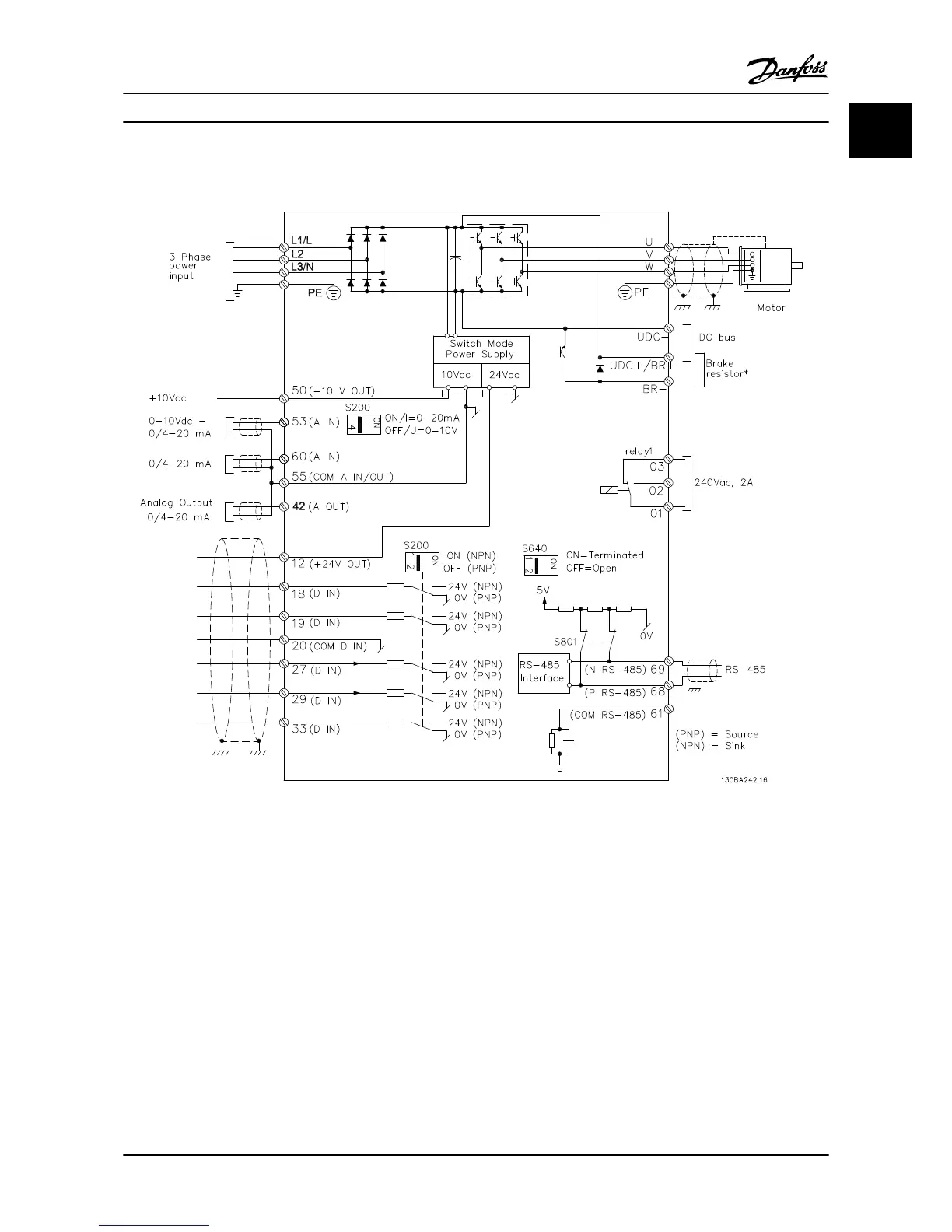
Figure 1.6 Diagram Showing all Electrical Terminals
* Brake (BR+ and BR-) are not applicable for frame M1.
Brake resistors are available from Danfoss.
Improved power factor and EMC performance can be
achieved by installing optional Danfoss line filters.
Danfoss power filters can also be used for load sharing.
1.3.8 Load Sharing/Brake
Use 0.25 in [6.3 mm] insulated Faston plugs designed for
high voltage for DC (load sharing and brake).
Contact Danfoss or see Instruction MI50N for load sharing
and Instruction MI90F for brake.
Load sharing: Connect terminals -UDC and +UDC/+BR.
Brake: Connect terminals -BR and +UDC/+BR (Not
applicable for frame M1).
NOTE!
Voltage levels of up to 850 V DC may occur between
terminals
+UDC/+BR and -UDC. Not short circuit-protected.
Quick Guide
VLT
®
Micro Drive Quick Guide
MG02B722 - VLT
®
is a registered Danfoss trademark 1-9
1 1
 Loading...


