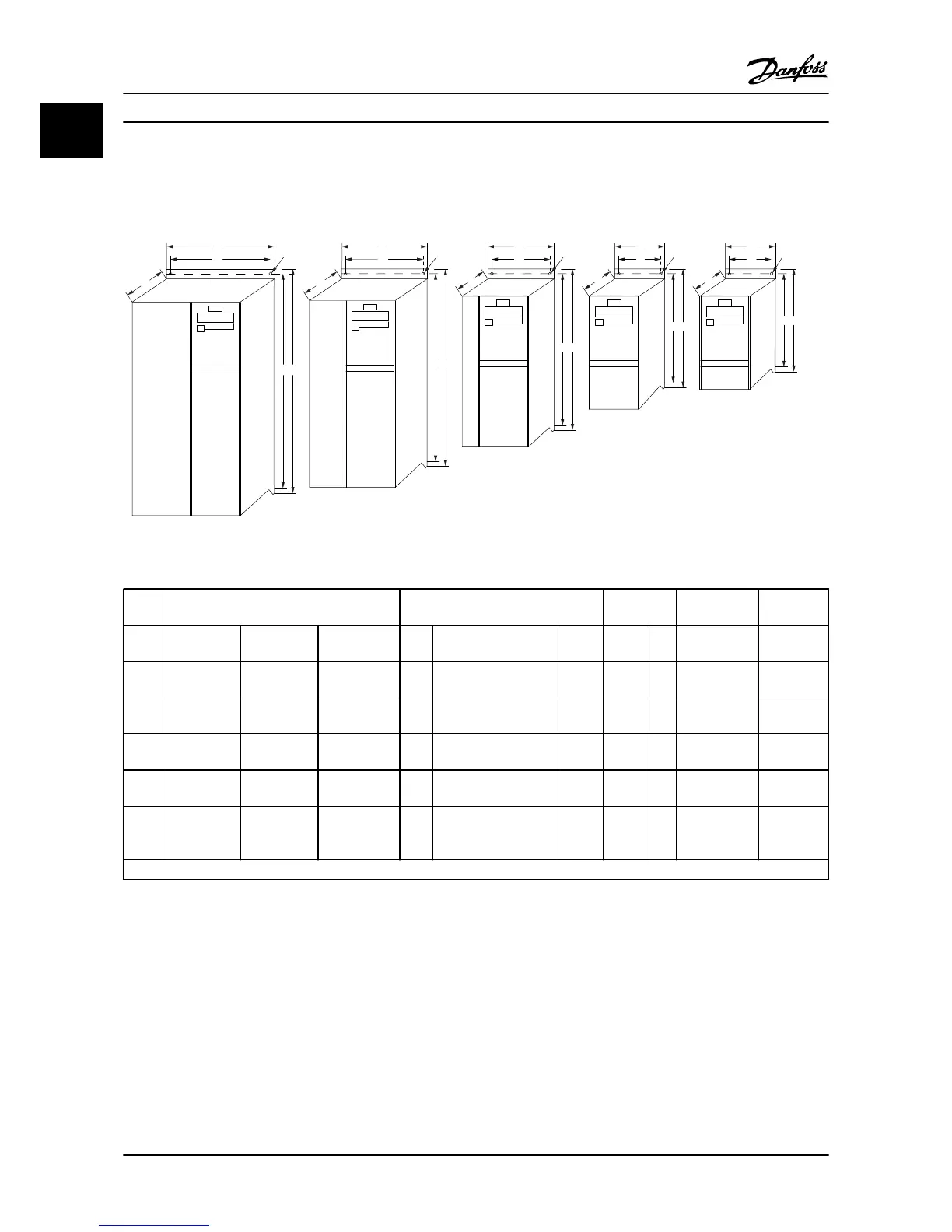
Figure 1.1 Mechanical Dimensions
Power [kW] Height (in [mm]) Width (in
[mm])
Depth
1)
(in
[mm])
Max. Weight
Frame 1X200–240 V 3X200–240 V 3X380–480 V A
A (incl. decoupling
plate)
a B b C lbs [kg]
M1
0.25–1 [0.18–
0.75]
0.34–1 [0.25–
0.75]
0.5–1 [0.37–
0.75]
5.91
[150]
8.1 [205]
5.53
[140.4]
2.76
[70]
2.17
[55]
5.83 [148] 2.43 [1.1]
M2 2 [1.5] 2 [1.5] 2–3 [1.5–2.2]
6.93
[176]
9.06 [230]
6.6
[166.4]
2.95
[75]
2.32
[59]
6.61 [168] 3.53 [1.6]
M3 3 [2.2] 3–5 [2.2–3.7] 4–10 [3.0–7.5]
9.41
[239]
11.58 [294]
8.9
[226]
3.54
[90]
2.72
[69]
7.64 [194] 6.6 [3.0]
M4
15–20 [11.0–
15.0]
11.5
[292]
13.7 [347.5]
10.72
[272.4]
4.92
[125]
3.82
[97]
9.5 [241] 13.23 [6.0]
M5
25–30 [18.5–
22.0]
13.2
[335]
15.26 [387.5]
12.4
[315]
6.5
[165]
5.51
[14
0]
9.76 [248] 20.94 [9.5]
1)
For LCP with potentiometer, add 0.3 in [7.6 mm].
Table 1.4 Mechanical Dimensions
1.3.3
Electrical Installation in General
NOTE!
All cabling must comply with national and local regulations on cable cross-sections and ambient temperature. Copper
conductors required, (140°–167°F [60°–75°C]) recommended.
Quick Guide
VLT
®
Micro Drive Quick Guide
1-4 MG02B722 - VLT
®
is a registered Danfoss trademark
11
 Loading...


