Enter line to common stator winding resistance
(Rs). If only line-line data is available, divide the
line-line value by 2 to achieve the line to
common (starpoint) value.
It is also possible to measure the value with an
ohmmeter, which also takes the resistance of the
cable into account. Divide the measured value by
2 and enter the result.
6. Parameter 1-37 d-axis Inductance (Ld).
Enter line to common direct axis inductance of
the PM motor.
If only line-line data is available, divide the line-
line value with 2 to achieve the line-common
(starpoint) value.
It is also possible to measure the value with an
inductance meter, which also takes the
inductance of the cable into account. Divide the
measured value by 2 and enter the result.
7. Parameter 1-40 Back EMF at 1000 RPM.
Enter line-to-line back EMF of PM motor at 1000
RPM mechanical speed (RMS value). Back EMF is
the voltage generated by a PM motor when no
adjustable frequency drive is connected and the
shaft is turned externally. Back EMF is normally
specied for nominal motor speed or for 1000
RPM measured between two lines. If the value is
not available for a motor speed of 1000 RPM,
calculate the correct value as follows: For
example, if back EMF at 1800 RPM is 320 V, the
back EMF at 1000 RPM is:
Back EMF=(Voltage/
RPM)x1000=(320/1800)x1000=178.
Program this value for parameter 1-40 Back EMF at
1000 RPM.
Test motor operation
1. Start the motor at low speed (100–200 RPM). If
the motor does not turn, check installation,
general programming and motor data.
Parking
This function is the recommended choice for applications
where the motor is rotating at slow speed (for example,
windmilling in fan applications). Parameter 2-06 Parking
Current and parameter 2-07 Parking Time are adjustable.
Increase the factory setting of these parameters for
applications with high inertia.
Start the motor at nominal speed. If the application does
not run well, check the VVC
+
PM settings. Table 5.13 shows
recommendations in dierent applications.
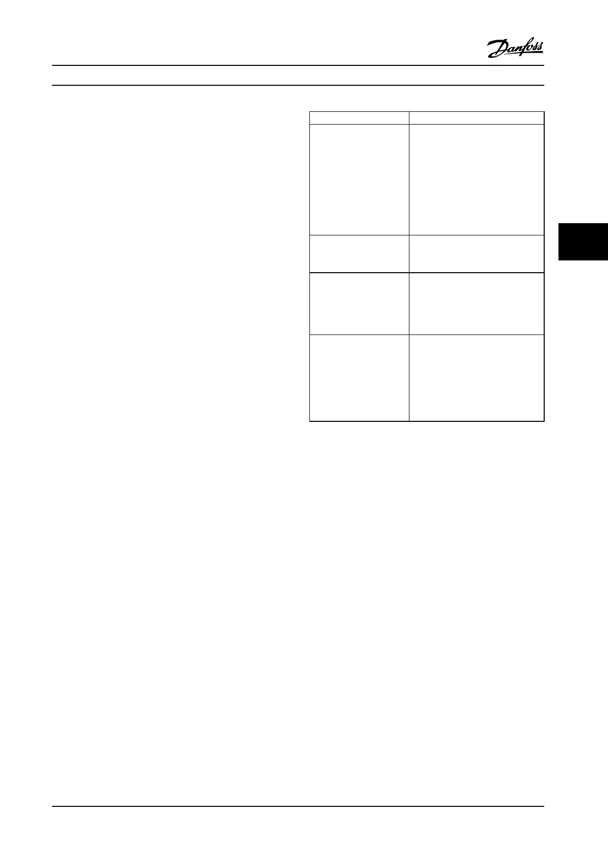
Application Settings
Low inertia applications
I
Load
/I
Motor
<5
•
Increase the value for
parameter 1-17 Voltage lter time
const. by factor 5–10.
•
Reduce the value for
parameter 1-14 Damping Gain.
•
Reduce the value (<100%) for
parameter 1-66 Min. Current at
Low Speed.
Medium inertia
applications
50>I
Load
/I
Motor
>5
Keep calculated values.
High inertia applications
I
Load
/I
Motor
> 50
Increase the values for
parameter 1-14 Damping Gain,
parameter 1-15 Low Speed Filter Time
Const. and parameter 1-16 High
Speed Filter Time Const.
High load at low speed
<30% (rated speed)
Increase the value for
parameter 1-17 Voltage lter time
const.
Increase the value for
parameter 1-66 Min. Current at Low
Speed (>100% for longer time can
overheat the motor).
Table 5.13 Recommendations for Dierent Applications
If the motor starts oscillating at a certain speed, increase
parameter 1-14 Damping Gain. Increase the value in small
steps.
Starting torque can be adjusted in parameter 1-66 Min.
Current at Low Speed. 100% provides nominal torque as
starting torque.
5.4.3 Automatic Motor Adaptation (AMA)
Automatic motor adaptation (AMA)
It is highly recommended to run AMA, because it measures
the electrical characteristics of the motor to optimize
compatibility between the adjustable frequency drive and
the motor under VVC
+
mode.
•
The adjustable frequency drive builds a
mathematical model of the motor for regulating
output motor current, thus enhancing motor
performance.
•
Some motors may be unable to run the complete
version of the test. In that case, select [2] Enable
reduced AMA in parameter 1-29 Automatic Motor
Adaption (AMA).
•
If warnings or alarms occur, see chapter 8.4 List of
Warnings and Alarms.
Commissioning Instruction Manual
MG07A122 Danfoss A/S © 11/2015 All rights reserved. 29
5 5
 Loading...


