30
INSTALLATION & SERVICE MANUAL FOR PROFESSIONALS
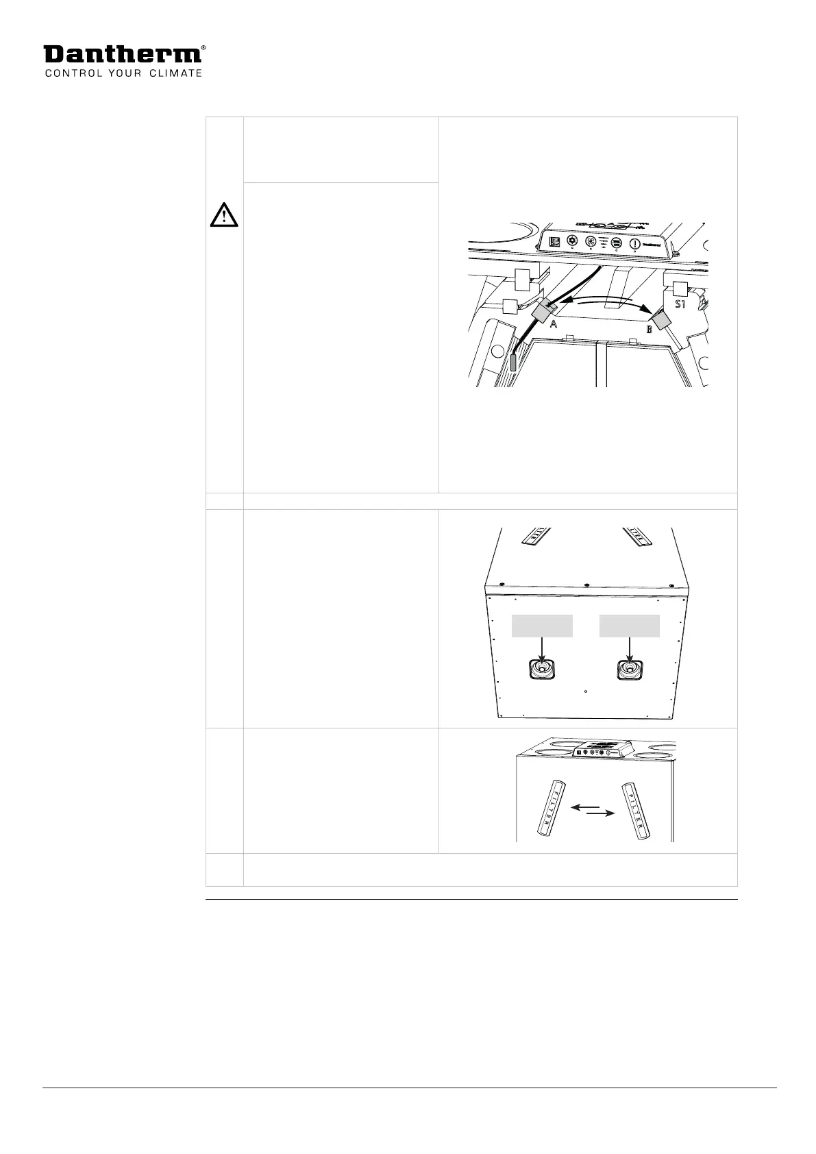
Installation Options: Switching between modes A and B
4 Move the cable port, incl. hu-
midity sensor (and VOC sensor, if
present), to the sensor position
for mode B.
CAUTION
Insucient device perfor-
mance and ventilation eect
To ensure optimal device
performance, all wired
accessories must be tted
correctly.
• Make sure that the distance
between the sensor head
and the cable port is
50mm to ensure correct
measurements of humidity
level (and air quality).
• All other wired accessories
must be swapped/installed
according to the current
operating mode A/B.
5 Ret the main PCB and housing and the front cover.
6 Switch the drain hose and set it
to mode B as indicated.
For a further description of how
to install the drain hose, see
page 36.
Mode B Mode A
7 Change the lter (ONLY if the
optional pollen lter ePM1>50%
is used).
• Check the table on page 18
to determine the correct posi-
tion of the ePM1>50% lter in
mode A/B.
8 Decide if you want to use the side or bottom outlet (described on page 31) and
then continue following the instructions of the section “Installation” on page 31.
 Loading...