7.2 Operating mode: DS2 (server) Host Interface (client)
At powering on the DS2 is the server and waits that that the client requests the connection. All this
happens thanks to a software application (socket) that allows to open the communication. Once there
is the connection DS2 periodically sends a packet at each scanning of the measurement information
according to the configuration. The host, which is the client, receives the packet and elaborates the
data. This is the only case where a response packet is not necessary.
7.2.1. Packet description
a. Complete binary scanning result (Complete beam status array) - 0x41 (‘A’ ASCII)
Sends to host the pattern with the binary information relative to each beam.
DS2 sends:
where:
n = 0x0E (600 mm model), 0x14 (900 mm model), 0x1A (1200 mm model), 0x23 (1650 mm
model)
aaa = 3 bytes with information concerning the 01-21 photoelements
bbb = 3 bytes with information concerning the 22-42 photoelements
ccc = 3 bytes with information concerning the 42-63 photoelements
zzz = 3 bytes with information concerning the last 21 photoelements
s = 1 byte indicating scanning status:
bit 0 = Power LED (0 OFF, 1 ON)
bit 1 = Failure LED (0 OFF, 1 ON)
bit 2 = Output LED (0 OFF, 1 ON)
bit 3 = PNP/NPN output (0 deactivated, 1 active)
bit 4 = Short-circuit output (0 no, 1 yes)
bit 5 = Misaligned photoelements or stability (0 no, 1 si)
bit 6 = n.a.
bit 7 = n.a.
x = checksum (complement to one of the Length, Type and Data field bytes sum)
Example:
Supposing to have the following data range:
0x01 0x02 0x03 0x04 0x05 0x06
the length will be 0x07 (one byte of the Type field plus six bytes of the Data field).
If the packet is a 0x41 type (‘A’ ASCII), then the checksum will be:
checksum = (0x07 + 0x41 + 0x01 + 0x02 + 0x03 + 0x04 + 0x05 + 0x06) XOR 0xFF = 0xA2
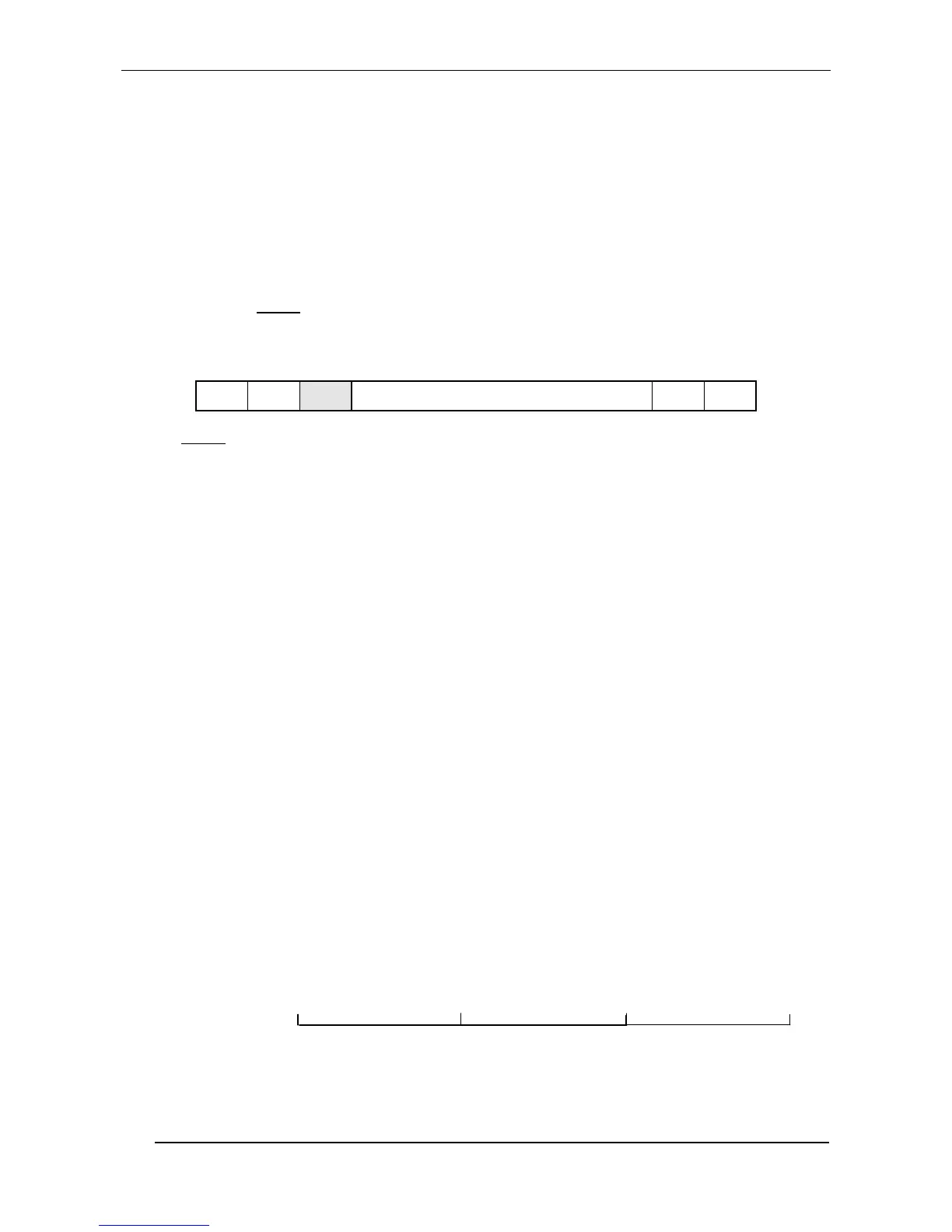
The correspondence between the photoelements (21) and the bits of a bytes tern is given below:
first byte second byte third byte
The position of one beam can be identified by the weight of the single bits, and the status from its
value from zero or one.
A bit at zero, indicates a non-obscured beam, and a bit at one indicates an obscured beam.

 Loading...