INSTALLATION
7
2
2.3 ELECTRICAL CONNECTIONS
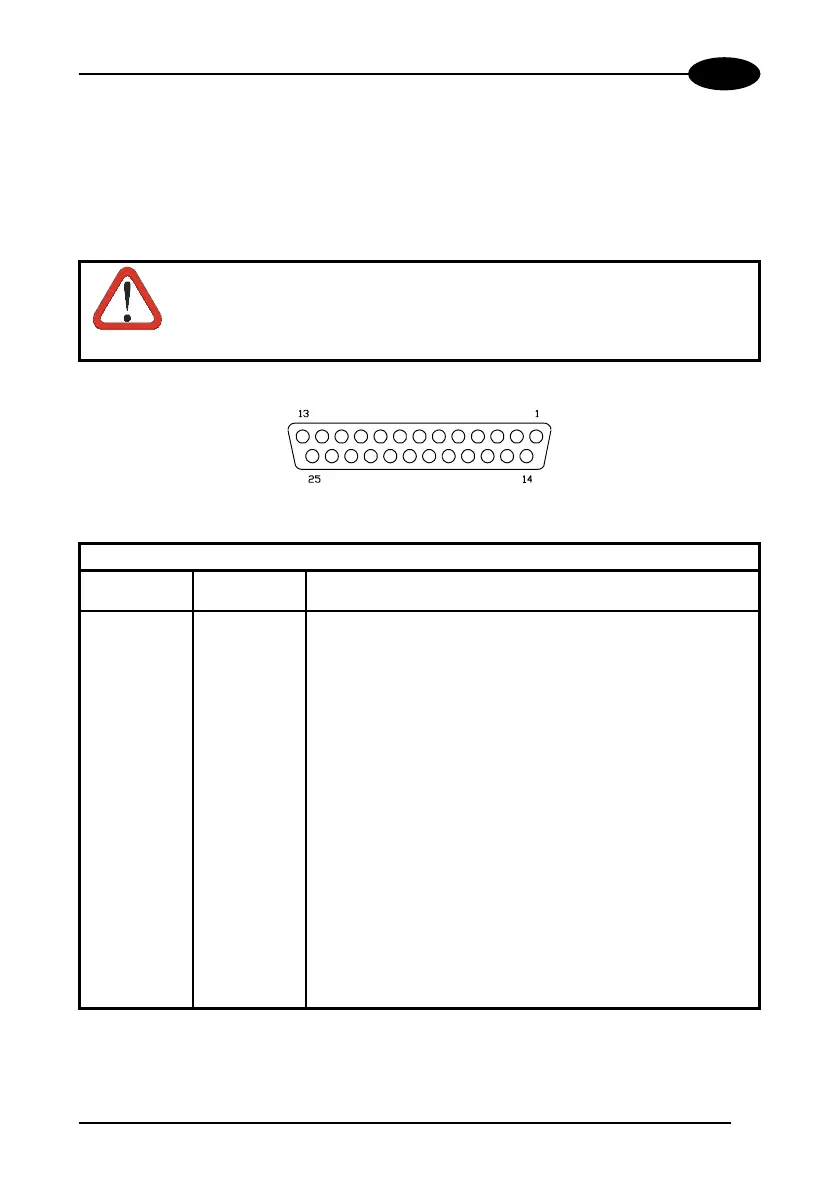
Several DS2100 models are equipped with a cable terminated by a 25-pin female D-
sub connector for connection to the power supply and input/output signals. The
details of the connector pins are indicated in the following table.
CAUTION
Do not connect GND and SGND to different (external) ground
references. GND and SGND are internally connected through
filtering circuitry which can be permanently damaged if subjected to
voltage drops over 0.8 Vdc.
Figure 4 - 25-pin female D-sub connector
25-pin D-sub connector pinout
Pin Name Function
13 VS Power supply input voltage +
25 GND Power supply input voltage -
1 CHASSIS Chassis Ground
9 VS External Trigger
supply voltage +
18 EXT TRIG+ External Trigger +
19 EXT TRIG- External Trigger -
8 OUT1 + Output 1 +
11 OUT2 + Output 2 +
12 OUT REF Output reference
22 OUT REF Output reference
20 RXAUX Auxiliary RS232
21 TXAUX Auxiliary RS232
23 CTSAUX Auxiliary handshake RS232
24 RTSAUX Auxiliary handshake RS232
6, 10, 14, 15,
16, 17
NC Not Connected
 Loading...