INSTALLATION
9
2
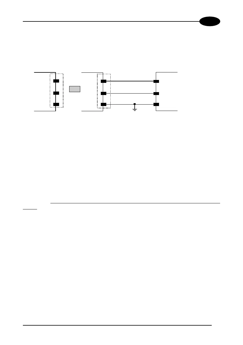
2.3.1 Power Supply
Power can be supplied to the scanner through the pins provided on the 25- or 9-pin
connector used for communication with the host (Figure 6):
Earth Ground
USER INTERFACE
CHASSIS
VGND
V+ (10 - 30 Vdc)
13
25
1
VS
GND
CHASSIS
DS2100 25-pin
or
7
5
1
VS
GND
CHASSIS
DS2100 9-pin
Figure 6 - Power supply connections
The power must be between 10 and 30 Vdc only.
It is recommended to connect pin 1 (CHASSIS) to a common earth ground.
2.3.2 Main Serial Interface
The signals relative to the following serial interface types are available on the
input/output connector of DS2100 depending on the DS2100 model (see par. 1.3).
A passive 20-mA Current Loop interface is available if the optional INT-22 accessory
is installed. This accessory interface replaces the main serial interface of the DS2100
model. The INT-22 accessory board is not available for DS2100-X3X0 models.
If the interface type is not compatible with the current communication handshaking,
then the system forces the handshake to none.
The parameters relative to the interface selected (baud rate, data bits, etc.) can
be defined using the WinHost utility program or "Host Mode" programming
procedure through ESC sequences installed from the diskette.
Details regarding the connections and use of the interfaces are given in the next
paragraphs.
 Loading...