12
3.3 Serial Communication
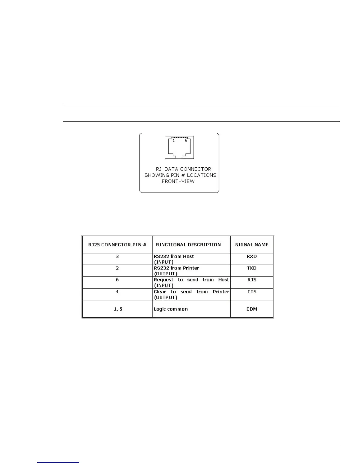
The RS232C Interface signals for the APEX 3 Series printers are terminated on a 6 PIN RJ
type data connector located on the side of the printer.
Six connections are provided from the Serial Interface to the host computer. Table 3 lists
the Serial Interface signals and pin outs for the RJ connector. The connector pin locations
are shown in Figure 11.
A minimum of two connections are required for operation: RXD – pin 3 and Common – pin
1
The communication parameters: Baud rate, Data Bit and Parity settings must
match those of the host device.
FIGURE 11 – RJ DATA CONNECTOR
TABLE 3 – APEX 3 Printers’ Serial RS232C Interface signals
Dip Switch #1 and #2 must be in <OFF> position to activate the serial communication
interface.
3.4 Infrared Communications Mode (IrDA)
Dip Switch #1 must be in the <ON> position.
The printer can be powered ON by pressing the power <On/Off> switch.
If no IrDA connection is made, the printer will automatically power down to a lower power
level to conserve battery life. It will remain in a “sleep” mode until an IrDA connection is
made, at which time the printer will “wake” and print the requested data.
Pressing the power switch again will turn the printer <OFF>.
 Loading...