• Two optional I/O modules
• One power supply module
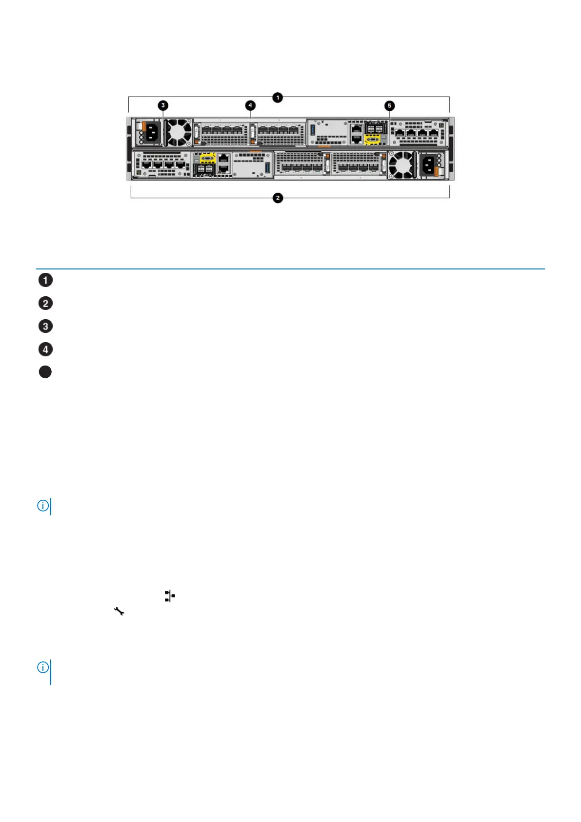
Figure 5. Base enclosure rear view with hardware component locations
Table 3. Base enclosure hardware component locations
Location Description
Node B
Node A
Power supply module
I/O module, slots 0 and 1
Embedded module
Base enclosure embedded modules and 4-port cards
About embedded modules
Each node contains one embedded module that can hold one 4-port card for front-end connectivity and internal communication between
nodes and appliances.
The first two ports of the 4-port card on the embedded module connect to a 10GbE/25GbE Ethernet switch.
NOTE: Both nodes must have the same type of embedded modules in the same slots.
The embedded module contains the following components:
• One 4-port card
• One non-maskable interrupt (NMI) button
• Two mini-SAS HD back-end ports
• Two RJ-45 LAN connectors
• System management port ( )
• Service port ( )
• One USB port
• One mini-serial port (unused)
• One DB9 serial port (unused)
NOTE:
The following figure shows the location of these components on the embedded module in node A. The locations
of the components in node B are mirrored.
Base enclosure component descriptions 9
 Loading...