9. Connect the Type-C power cable to the connector on the Input Output board. Adhere the Type-C power cable onto the
system board and Input Output board.
Next steps
1. Install the WWAN card for 4G LTE enabled systems.
2. Install the base cover.
3. Follow the procedure in after working inside your computer.
System board
Removing the system board
Prerequisites
1. Follow the procedure in before working inside your computer.
2. Remove the base cover.
3. Remove the battery.
4. Remove the SIM card.
About this task
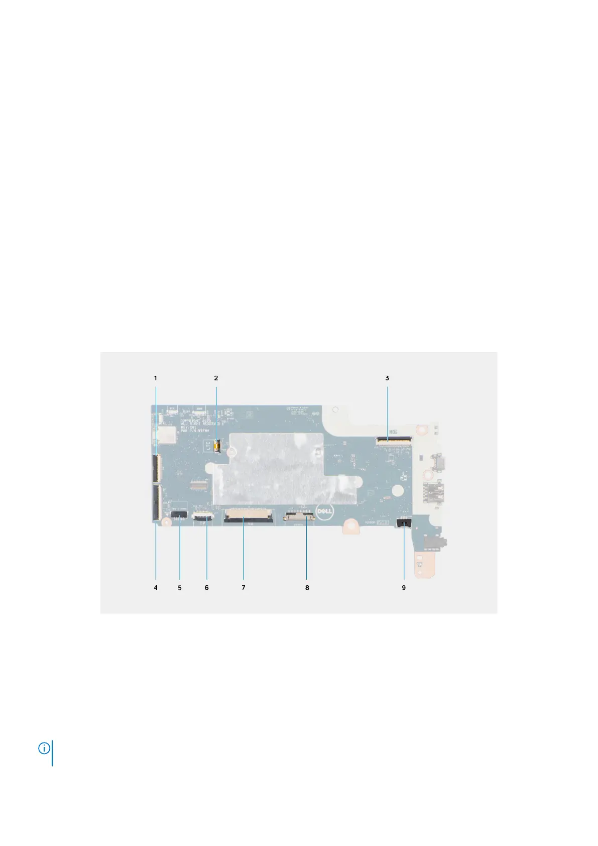
The following image indicates the connectors on your system board.
Figure 1. System-board connectors
1.
30-pin FFC Input Output board cable ( 30-pin FPC Input
Output board cable for systems enabled with 4G LTE)
2. LTE signal cable (For systems enabled with 4G LTE)
3. Display cable 4. 40-pin FFC Input Output board cable
5. Type-C power cable 6. Touchpad cable
7. Keyboard cable 8. Battery cable
9. Speaker cable
The following images indicate the location of the system board and provide a visual representation of the removal procedure.
NOTE:
The following image is from 4G LTE enabled systems. For WiFi enabled systems, the system board has a different
configuration.
34 Removing and installing components
 Loading...