About this task
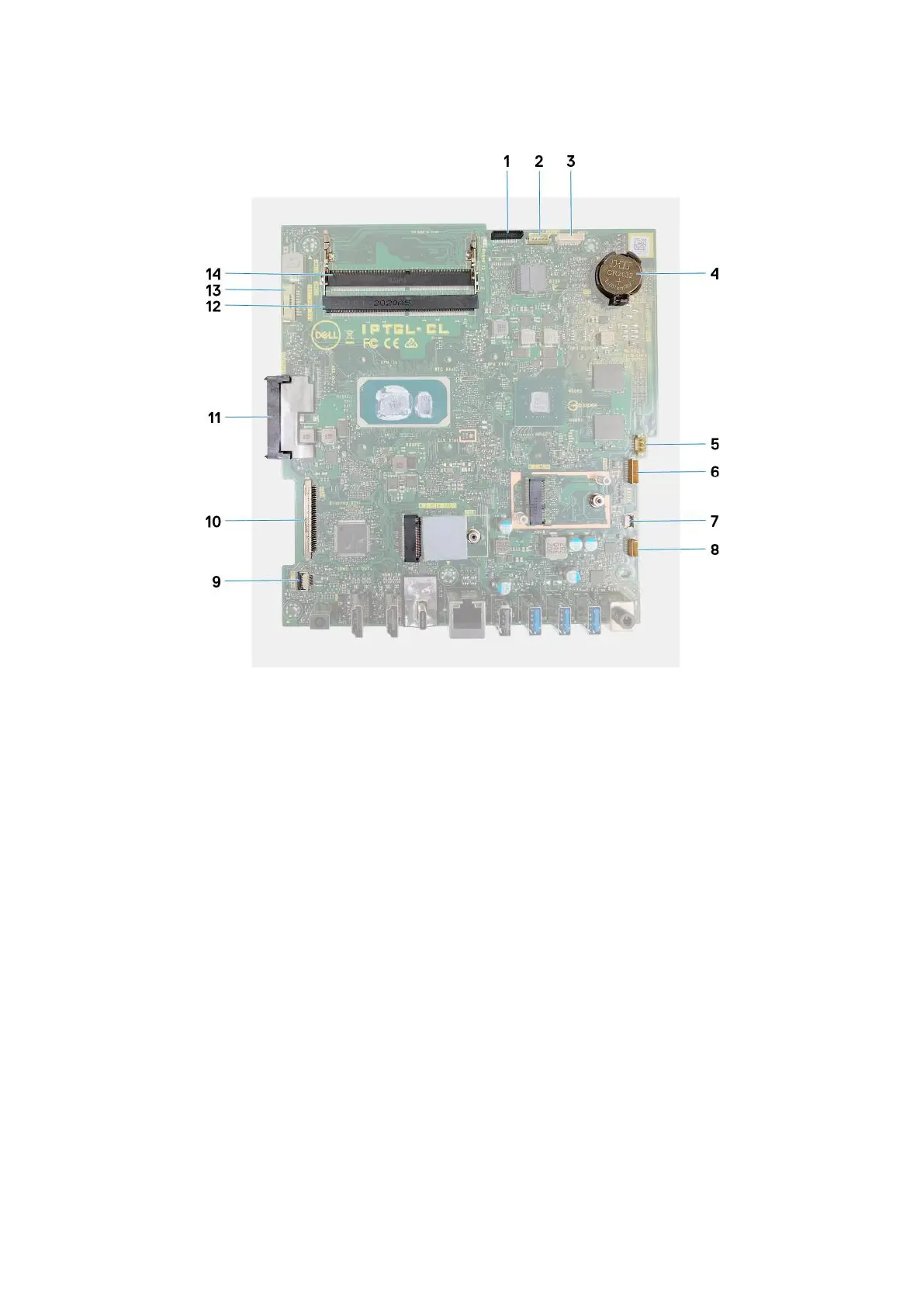
The following image indicates the connectors on your system board.
Figure 2. System-board connectors
1.
Camera cable 2. Touchscreen cable
3. Debug port 4. Coin-cell battery
5. Fan cable 6. Microphones cable
7. Media-card reader cable 8. Speaker cable
9. Power-button board cable 10. Display cable
11. Hard-drive connector 12. Memory module (DIMM2)
13. Backlit cable 14. Memory module (DIMM1)
The following image indicates the location of system board and provides a visual representation of the installation procedure.
Steps
1. Align the screw holes on the system board with the screw holes on the display-assembly base.
2. Replace the five screws (M3x5) that secure the system board to the display-assembly base.
3. Connect the camera cable to the system board.
4. Connect the touchscreen cable to the system board.
5. Connect the fan cable to the system board.
6. Connect the microphone-module cable to the system board.
7. Connect the media-card reader cable to the system board.
8. Connect the speaker cable to the system board.
9. Connect the power-button board cable to the system board and close the latch to secure the cable.
10. Connect the display cable to the system board.
11. Connect the backlit cable to the system board.
48
Removing and installing components
 Loading...