installed and running), you can remove and replace one PSU while the other PSU is
running without disrupting traffic.
Fans
The S5000 supports two fan trays with airflow directions from I/O to Utility or Utility to I/O.
Do not mix I/O to Utility and Utility to I/O airflows in a single S5000 chassis. All fans and
PSUs in a configuration must be in the same airflow direction. If you create a mixed
airflow configuration, the software notifies you of the invalid configuration.
The fans must be installed at the customer site.
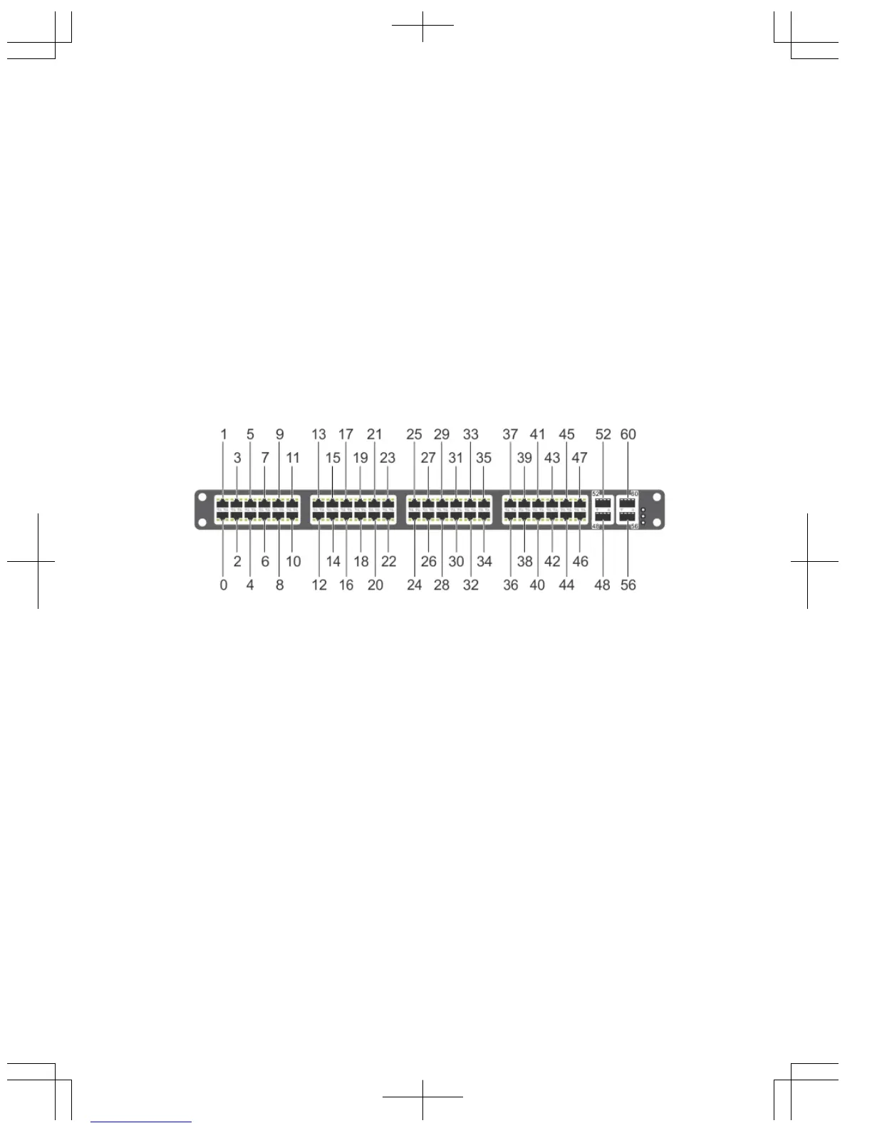
Port Numbering Convention
Even-numbered ports are at the bottom of the I/O panel and for modules odd-numbered
ports are at the top of the I/O panel.
Figure 4. Port Numbering
The previous figure shows the fixed four 40GbE data ports (ports 48, 52, 56, and 60) and
the four slots for pluggable modules on the S5000 I/ O panel. You can also use the 40GbE
ports in 4 × 10GbE mode.
The S5000 supports the following possible modules:
• 12-Port Ethernet Module (1G/10G speeds) (slot 0, 1, 2, or 3)
• 12-Port Fibre Channel Module (2G/4G/8G speeds) (slot 0)
The valid slot numbers are stack-unit numbers (from 0 to 11). The valid port numbers for
each interface type are:
• 1GbE: Ports 0 to 47
• 10GbE: Ports 0 to 63
• 40GbE: Ports 48, 52, 56, and 60
• Fibre Channel: Ports 0 to 11
8
 Loading...