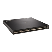
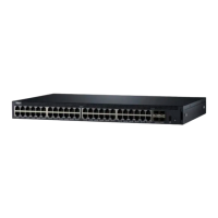
1. Slot 0 (supports Ethernet and Fibre
Channel modules)
2. Slot 1 (supports only Ethernet
modules)
3. Slot 2 (supports only Ethernet
modules)
4. Slot 3 (supports only Ethernet
modules)
5. Four 40GbE QSFP+ ports (each port
ALSO supports 4 × 10GbE mode)
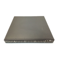
NOTE: The LED displays for the system status are on both sides of the chassis. The
fan and power status LEDs are on the Utility panel.
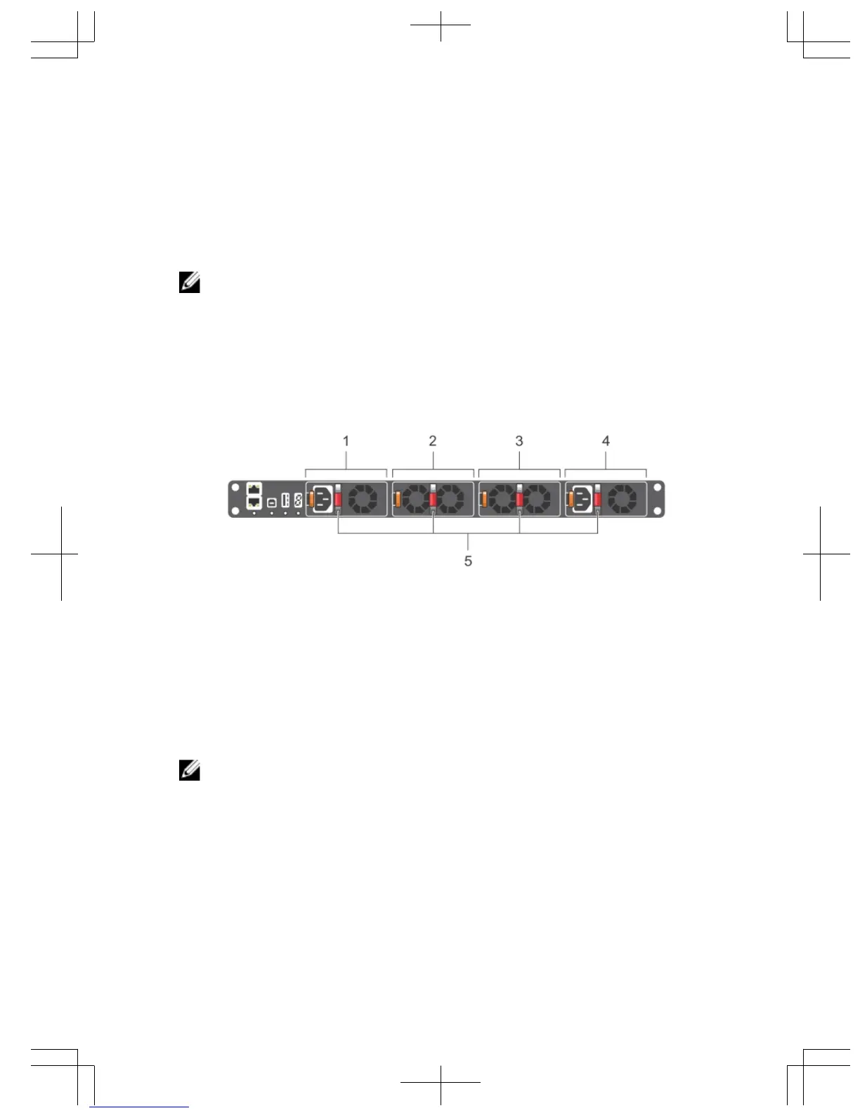
Utility Panel
The Utility panel side of the platform contains the fan and power modules.
Figure 3. S5000 Power Supplies and Fan Modules
1. Slot 0 (for PSU 0)
2. Slot 1 (for Fan Module 0)
3. Slot 2 (for Fan Module 1)
4. Slot 3 (for PSU 1)
5. Grab Handles
Power Supplies
The S5000 supports two hot-swappable PSUs.
NOTE: The PSUs must be installed at the customer site.
The S5000 has SKUs that support the following configurations:
• AC PSU with fan airflow from I/O to Utility
• AC-R PSU with fan airflow from Utility to I/O
• DC PSU with fan airflow from I/O to Utility
• DC-R PSU with fan airflow from Utility to I/O
PSUs are field replaceable. To ensure power redundancy and adequate cooling, install
two power supplies in the switch. When running with full redundancy (two PSUs
7
 Loading...