EasyManuals Logo

Dell PowerEdge T410 User Manual

Dell PowerEdge T410
204 pages
To Next Page IconTo Next Page
To Previous Page IconTo Previous Page
Page #110 background image
110 Installing System Components
1. Requires x4- or x8-based memory modules.
Installing Memory Modules
WARNING: Only trained service technicians are authorized to remove the system
cover and access any of the components inside the system. Before you begin this
procedure, review the safety instructions that came with the system.
WARNING: The memory modules are hot to the touch for some time after the
system has been powered down. Allow time for the memory modules to cool
before handling them. Handle the memory modules by the card edges and avoid
touching the components on the memory module.
CAUTION: To ensure proper system cooling, memory-module blanks must be
installed in any memory socket that is not occupied. Remove memory-module
blanks only if you intend to install memory in those sockets.
1
Turn off the system, including any attached peripherals, and disconnect
the system from the electrical outlet and peripherals.
2
Rotate the system feet inward and lay the system on a flat surface.
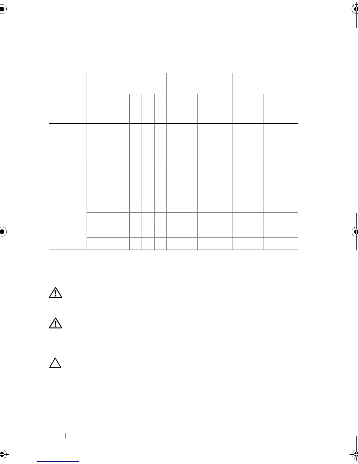
Table 3-2. Sample UDIMM Memory Configurations (Per Processor)
Memory
Mode
Memory
Module
Size
Memory
Sockets
Single Processor Dual Processor
4 1 2 3 Physical
Memory
(GB)
Available
Memory
(GB)
Physical
Memory
(GB)
Available
Memory
(GB)
Optimizer 1-GB
X
X
X
X
X
X
X
X
X
X
1
2
3
4
all 2
4
6
8
all
2-GB
X
X
X
X
X
X
X
X
X
X
2
4
6
8
all 4
8
12
16
all
Advanced
ECC
1
1-GB XX 2 all 4 all
2-GB XX 4 all 8 all
Mirroring 1-GB XX 2142
2-GB XX 4284
book.book Page 110 Tuesday, June 9, 2009 4:09 PM

Table of Contents

Other manuals for Dell PowerEdge T410

Questions and Answers:

Question and Answer IconNeed help?

Do you have a question about the Dell PowerEdge T410 and is the answer not in the manual?

Dell PowerEdge T410 Specifications

General IconGeneral
Tcase77.6 °C
Bus typeQPI
SteppingB1
FSB ParityNo
Processor codeSLBV4
Processor cache12 MB
Processor cores4
Processor modelE5620
System bus rate5.86 GT/s
Processor seriesIntel Xeon 5600 Series
Processor socketSocket B (LGA 1366)
Processor threads8
Processor codenameWestmere EP
Motherboard chipsetIntel® 5500
Number of QPI links2
Processor frequency2.4 GHz
Processor cache typeSmart Cache
Processor lithography32 nm
Processor manufacturerIntel
Processor package size42.5 X 45 mm
Processor front side bus- MHz
Processor boost frequency2.66 GHz
Processor operating modes64-bit
ECC supported by processorYes
Supported instruction setsSSE4.2
Thermal Design Power (TDP)80 W
Number of processors installed1
CPU multiplier (bus/core ratio)18
Physical Address Extension (PAE)40 bit
Memory types supported by processorDDR3 800/1066
Memory channels supported by processorTriple
Memory clock speeds supported by processor800, 1066 MHz
Memory bandwidth supported by processor (max)25.6 GB/s
Maximum internal memory supported by processor288 GB
HDD size3.5 \
Optical drive typeDVD-RW
Total storage capacity250 GB
Maximum storage capacity12 TB
Number of HDDs supported6
Memory slots8x DIMM
Internal memory4 GB
Memory clock speed1066 MHz
Internal memory typeDDR3-SDRAM
Maximum internal memory16 GB
Maximum graphics card memory8 MB
Graphics cardG200eW
Dimensions (W x D x H) (imperial)8.58 x 24.28 x 17.52 \
Networking featuresGigabit Ethernet
PS/2 ports quantity0
USB 2.0 ports quantityUSB 2.0 ports have a data transmission speed of 480 Mbps, and are backwards compatible with USB 1.1 ports. You can connect all kinds of peripheral devices to them.
Number of power supply units-
Compatible operating systemsMicrosoft SQL Server 2008 R2/Windows Small Business Server 2008/Essential Business Server 2008/Server 2008 SP2, x86/x64/Server 2008 R2/HPC Server 2008; Novell SUSE Linux Enterprise Server; Red Hat Enterprise Linux.
Chassis typeTower
Processor ARK ID47925
Intel® Turbo Boost Technology1.0
Weight and Dimensions IconWeight and Dimensions
Depth616.8 mm
Width217.9 mm
Height444.9 mm

Related product manuals