6
ASSEMBLING STAND
AND RUBBER FEET
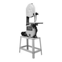
1. Assemble the stand, as shown in Fig. 3, using the
32 carriage bolts, flat washers and nuts supplied. The
two 12-3/4" long upper braces (J); 21-1/2" long upper
braces (K); 17" long lower braces (L) and 25-3/4" long
lower braces (M) should be fastened to the four 26-1/4"
long legs (B). IMPORTANT: The top lips of the upper
braces (J) should be on top of the top lips of upper
braces (K).
2. Assemble the four rubber feet (E) Fig. 3, to bottom of
each leg (B) as shown.
ASSEMBLY INSTRUCTIONS
WARNING: FOR YOUR OWN SAFETY, DO NOT CONNECT THE BAND SAW TO THE POWER
SOURCE UNTIL THE MACHINE IS COMPLETELY ASSEMBLED AND YOU HAVE READ AND
UNDERSTOOD THE ENTIRE OWNERS MANUAL.
ASSEMBLING BAND SAW
TO STAND
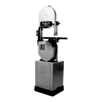
1. Fig. 4 illustrates the two through holes (A) and two
threaded holes (C) which will be used to secure the band
saw to the stand.
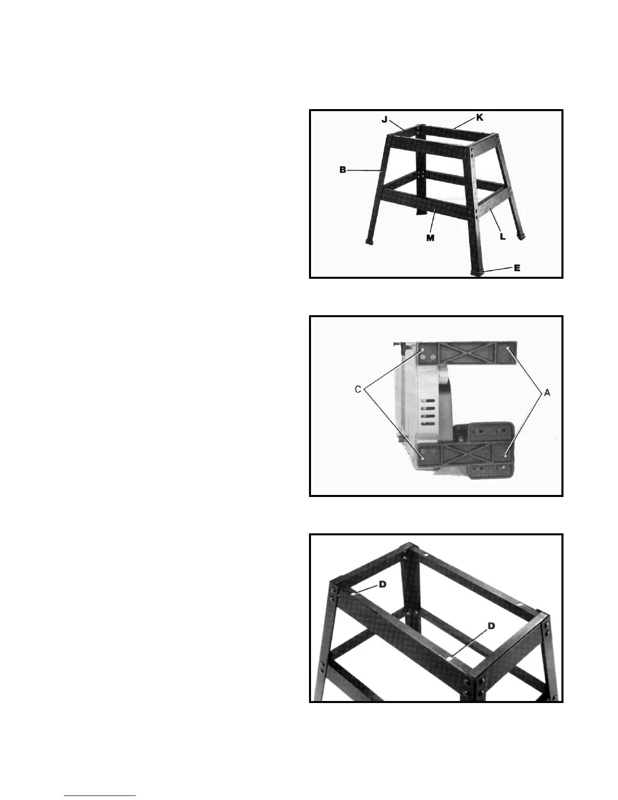
2. Place the band saw on top of stand and line up the
two threaded holes (C) Fig. 4, with the two holes (D) Fig.
5, on upper brace of stand.
Fig. 5
Fig. 4
Fig. 3
 Loading...