Home
Delta
Servo Drives
ASD-A2R-0421 Series
Delta ASD-A2R-0421 Series User Manual
4
of 1
of 1 rating
660 pages
Give review
Manual
Specs
To Next Page
To Next Page
To Previous Page
To Previous Page
Loading...
Chapter 1
1 Specifications
ASDA-A2R Series
11-20
Revision December, 2014
1
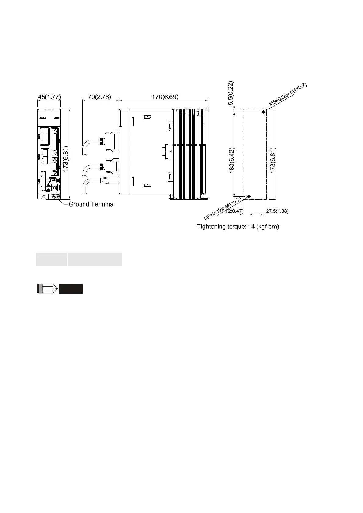
1.7 Dimensions of the Servo Drive
ASD-A2R-0121; ASD-A2R-0221; AS
D-A2R-0421 (100W ~ 400W)
Weight
1.5
(
3.3
)
NO
T
E
1)
Dimensions are in millimeters (i
nches); Weights are in kilograms
(pounds).
2)
Dimensions and weights might be
revised without prior notice.
595
597
Table of Contents
Default Chapter
7
Table of Contents
7
Revision
15
Chapter 1 Inspection and Model Explanation
17
Inspection
17
Product Model
19
Nameplate Information
19
Model Explanation
21
Servo Drive and Corresponding Servo Motor
25
Each Part of the Servo Drive
26
ECML Series Servo Motor
29
Chapter 2 Installation
31
Notes
31
Ambient Conditions of Storage
31
Ambient Conditions of Installation
32
Installation Direction and Space
33
Specification of Circuit Breaker and Fuse
34
EMI Filters Selection
35
Selection of Regenerative Resistor
37
Chapter 3 Wiring
49
Wiring of Delta's Servo System
49
Wiring Diagram of Peripheral Devices
49
Communication Type)
49
Connectors and Terminals of the Servo Drive
51
Wiring Method
53
Specification of ECMA Motor U, V, W Power Cable
55
Specification of ECML Motor U, V, W Power Cable
57
Specification of Connector of Encoder Cable
58
Specification and Definition of Motor Signal Cable
61
Selection of Wire Rod
62
Schematic Diagram of Servo System
64
I/O Signal (CN1) Connection
66
I/O Signal (CN1) Connector Terminal Layout
66
Explanation of I/O (CN1) Connector Signal
68
Wiring Diagram (CN1)
79
The DI and DO Signal Specified by the User
87
Application: Wiring of CN1 Quick Connector
88
CN2 Connector
91
Wiring of CN3 Connector
94
Layout of CN3 Connector
94
Connection between CN3 Connector and Personal Computer
95
CN4 Serial Connector (USB)
96
CN5 Connector (Full-Closed Loop)
97
CN6 Connector (Canopen)
98
Extension Digital Input Connector of CN7
100
Standard Wiring Method
101
Position (PT) Mode Standard Wiring
101
Position (PR) Mode Standard Wiring
102
Speed Mode Standard Wiring
103
Torque Mode Standard Wiring
104
Canopen Mode Standard Wiring
105
Wiring System of Other Brand of Motor
106
Wiring Diagram of Peripheral Devices
106
Specification of Definition of ECML Motor Cable
110
Signal Converter Box
112
Chapter 4 Panel Display and Operation
117
Panel Description
117
Parameter Setting Procedure
118
Status Display
121
Setting Saved Display
121
Decimal Point
121
Alarm Message
121
Positive and Negative Sign Setting
121
Monitor Display
122
General Function
125
Operation of Fault Record Display
125
JOG Mode
126
Force DO Output
127
Digital Input Diagnosis Operation
128
Digital Output Diagnosis Operation
128
Chapter 5 Trial Operation and Tuning
129
Inspection Without Load
129
Apply Power to the Servo Drive
130
JOG Trial Run Without Load
133
Trial Run Without Load (Speed Mode)
134
Trial Run Without Load (Position Mode)
137
Tuning Procedure
139
Flowchart of Tuning Procedure
141
Inertia Estimation Flowchart (with Mechanism)
142
Flowchart of Auto Tuning
143
Flowchart of Semi-Auto Tuning
144
Limit of Inertia Ratio for Rotary Motor / Total Weight of Linear Motor and
145
Load (Kg)
145
Mechanical Resonance Suppression Method
148
Tuning Mode and Parameters
149
Tuning in Manual Mode
150
Chapter 6 Control Mode and Operation
153
Selection of Operation Mode
153
Position Mode
155
Position Command in PT Mode
155
Position Command in PR Mode
155
Control Structure of Position Mode
156
S-Curve Filter (Position)
158
Electronic Gear Ratio
160
Low-Pass Filter
161
Timing Diagram in Position Mode (PR)
162
Gain Adjustment of Position Loop
163
Low-Frequency Vibration Suppression in Position Mode
164
Speed Mode
167
Selection of Speed Command
167
Control Structure of Speed Mode
168
Smooth Speed Command
170
The Scaling of Analog Command
172
The Timing Diagram in Speed Mode
172
Gain Adjustment of Speed Loop
173
Resonance Suppression
178
Torque (Force) Mode
183
Selection of Torque (Force) Command
183
Control Structure of Torque (Force) Mode
184
Smooth Torque (Force) Command
185
The Scaling of Analog Command
185
The Timing Diagram in Torque (Force) Mode
186
Dual Mode
187
Speed / Position Dual Mode
188
Speed / Torque (Force) Dual Mode
188
Torque (Force) / Position Dual Mode
189
Others
190
The Use of Speed Limit
190
The Use of Torque (Force) Limit
190
Analog Monitor
191
The Use of Brake
192
Chapter 7 Motion Control
195
Motion Control Functions of ASDA-A2R
195
Information of the Servo Drive
195
Description of Monitor Variables
197
Description of Data Array
203
Description of Motion Axes
206
Description of PR Mode
207
The Difference between General PR Mode and the One in ASDA-A2R
207
The Position Unit of PR Mode
208
Description of Register in PR Mode
208
Homing Description of PR Mode
210
DI/DO Provided by PR Mode and Diagrams
210
Parameter Settings in PR Mode
212
Programming the Path in PR Mode
218
The Description of E-Cam Function
220
Function Description of CAPTURE (Data Capture)
228
Function Description of COMPARE (Data Compare)
230
Chapter 8 Parameters
233
Parameter Definition
233
List of Parameters
234
Parameter Description
248
P0-XX Monitor Parameters
248
P1-XX Basic Parameters
268
P2-XX Extension Parameters
313
P3-XX Communication Parameters
351
P4-XX Diagnosis Parameters
358
P5-XX Motion Setting Parameters
370
P6-XX PR Parameters
439
P7-XX PR Parameters
478
PM-XX Motor Parameters
489
Table 8.1 Function Description of Digital Input (DI)
511
Table 8.2 Function Description of Digital Output (DO)
518
Chapter 9 Communication
525
RS-232 Communication Hardware Interface
525
RS-485/RS-232 Communication Parameters Setting
527
MODBUS Communication Protocol
528
Write-In and Read-Out Communication Parameters
539
Chapter 10 Toubleshooting
541
Alarm of Servo Drive
541
Alarm of Canopen Communication
544
Alarm of Motion Control
546
Causes and Corrective Actions
550
Corrective Actions after the Alarm Occurs
572
Chapter 11 Specifications
577
Specifications of Servo Drive
577
Specifications of Servo Motor (ECMA Series)
580
Specifications of Servo Motor (ECML Series)
588
Torque Features (T-N Curve)
590
Force and Speed Features (F-S Curve)
592
Overload Features
594
Dimensions of the Servo Drive
596
Dimensions of ECMA Series Servo Motor
599
Dimensions of ECML Series Servo Motor
604
Chapter 12 Setting of Motor Parameters
607
Tuning Procedure of Motor Parameters
607
4
Based on 1 rating
Ask a question
Give review
Questions and Answers:
Need help?
Do you have a question about the Delta ASD-A2R-0421 Series and is the answer not in the manual?
Ask a question
Delta ASD-A2R-0421 Series Specifications
General
Brand
Delta
Model
ASD-A2R-0421 Series
Category
Servo Drives
Language
English
Related product manuals
Delta ASD-A2R-0221 Series
660 pages
Delta ASD-A2R-1B43 Series
660 pages
Delta ASD-A2 Series
721 pages
Delta ASD-A2-1021 Series
721 pages
Delta ASD-A2-5523 Series
721 pages
Delta ASD-A2-2023 Series
721 pages
Delta ASD-A2-4543 Series
721 pages
Delta ASD-A2-3023 Series
721 pages
Delta ASD-A2-2043 Series
721 pages
Delta ASD-A2-3043 Series
721 pages
Delta ASD-A2-0421 Series
721 pages
Delta ASD-A2-5543 Series
721 pages
 Loading...
