Chapter 6 Control Circuit Terminals MS300 (IP66 / NEMA 4X)
6-4
6-1 Control Circuit Terminal Specifications
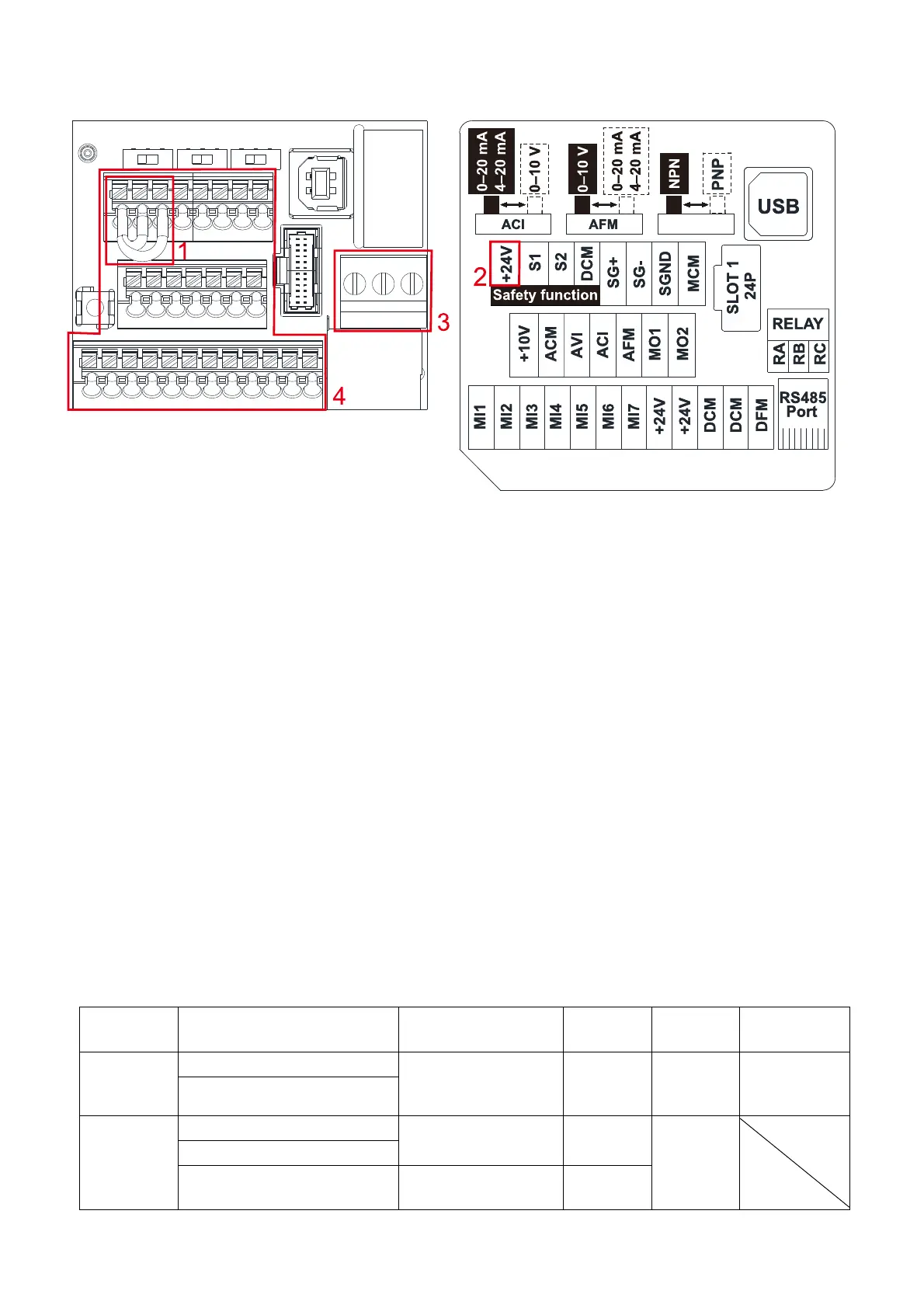
Control Circuit Terminal Distribution Diagram
Figure 6-6
Control Circuit Terminal Location Map
Figure 6-7
Wiring precautions:
1. The factory default condition is +24 V/ S1/ S2 shorted by jumper, as shown in the block 1 of the
figure above. Refer to the Figure 4-2 in Chapter 4 WIRING for more details.
2. The +24 V power supply for safety function, as shown in the block 2 of the figure above. This is only
for STO use and cannot be used for other purposes.
3. The RELAY terminal uses the PCB terminal block (as shown in the block 3 of the figure above):
Tighten the wiring with a 3.5 mm width and 0.6 mm thickness slotted screwdriver.
The ideal length of stripped wire at the connection side is 6–7 mm.
When wiring bare wires, make sure they are perfectly arranged to go through the wiring holes.
4. The control circuit terminal uses a spring clamp terminal block (as shown in the block 4 of the figure
above):
Tighten the wiring with a 2.5 mm width and 0.4 mm thickness slotted screwdriver.
The ideal length of stripped wire at the connection side is 9 mm.
Wiring Specifications of Control Circuit Terminals:
Terminal
Name
Wiring Specifications of
Control Circuit Terminals
Length of Stripped
Wire (mm)
Max. Wire
Gauge
Min. Wire
Gauge
Torque
RELAY
Terminal
Solid
6–7
1.5 mm
2
[16 AWG]
0.2 mm
2
[24 AWG]
5 kg-cm
[4.3 lb-in.]
[0.49 Nm]
Strand
Control
Circuit
Terminal
Solid
9
0.75 mm
2
[18 AWG]
0.25 mm
2
[24 AWG]
Strand
Stranded with ferrules with
plastic sleeve
9
0.5 mm
2
[20 AWG]
Table 6-1
 Loading...