DVP-ES2/EX2/EC5/SS2/SA2/SX2/SE&TP Operation Manual - Programming
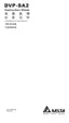
previous step is completed, therefore it forms a sequential control process similar to SFC
(Sequential Function Chart) mode. The STL sequence can be converted into a PLC ladder diagram
which is called “step ladder diagram” as below.
e
S0
S21
S22
M1002
initial
pulse
M1002
SET
S0
SET
S21
S
S0
SET
S22
S
S21
S
S22
S0
RET
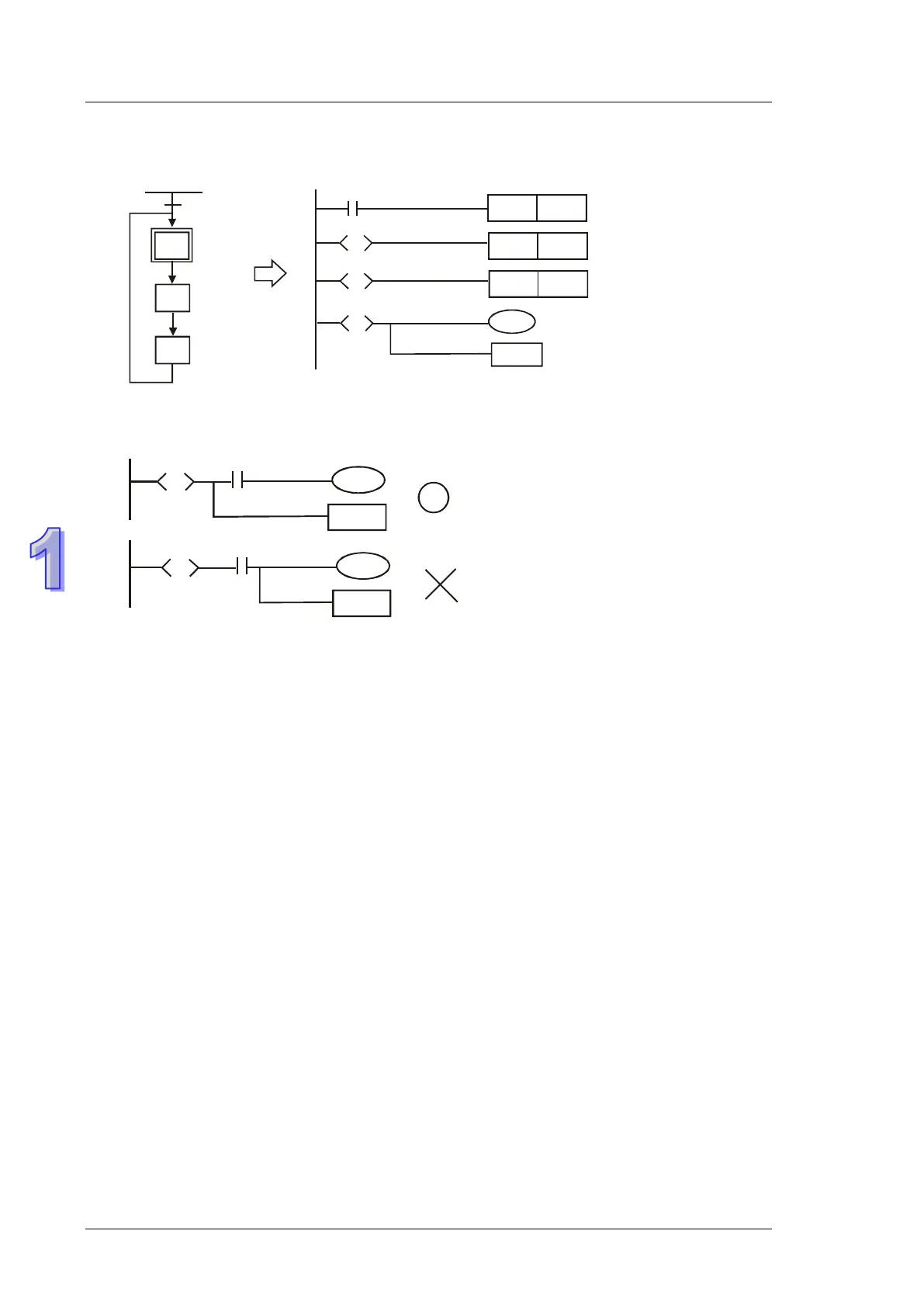
1.5.12 RET (Return)
RET instruction has to be placed at the end of sequential control process to indicate the completion
of STL flow.
Note: Always connect RET instruction immediately after the last step point indicated as the above
diagram otherwise program error may occur.
 Loading...