Ethernet Communication Module DVPEN01-SL
DVP-PLC Operation Manual
45
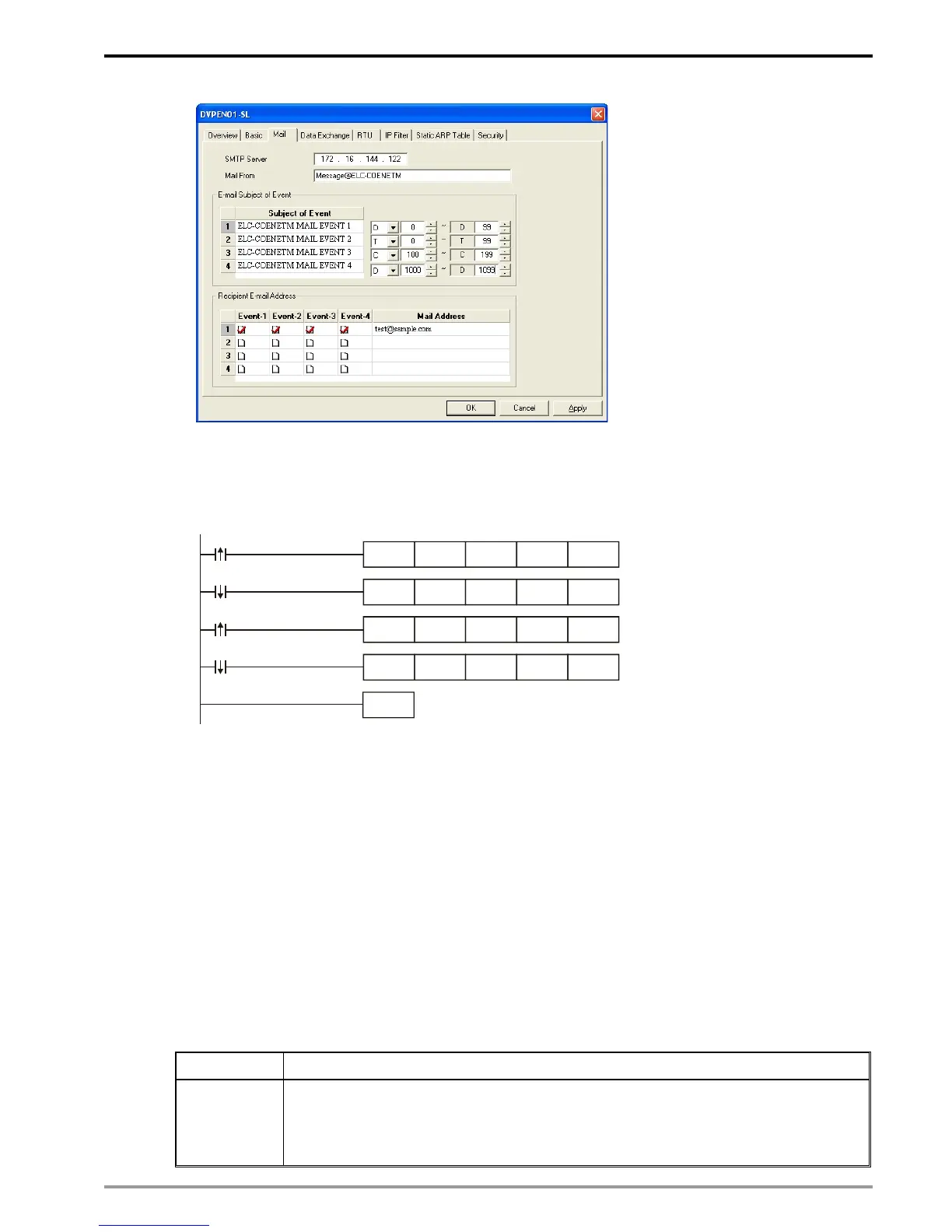
4. Switch to “Select Recipients” page. Check all the boxes of “Recipient 1”. Click on “OK” to complete
the setting.
5. After all the settings in DVPEN01-SL are completed, compile the ladder diagram in the MPU and
download it to the MPU. See below for the program design:
END
X0
T0 K100 K3 K1
K4
K5
K6
K1
X0
T0 K100 K1 K1
T0 K100
K1 K1
T0 K100
K1 K1
Y0
Y0
Explanations:
• If the rising-edge of X0 is triggered, X0 will go from Off to On. Write “1” into CR#3 of
DVPEN01-SL, and the first E-Mail will be sent out.
• If the falling-edge of X0 is triggered, X0 will go from On to Off. Write “1” into CR#4 of
DVPEN01-SL, and the second E-Mail will be sent out.
• If the rising-edge of Y0 is triggered, Y0 will go from Off to On. Write “1” into CR#5 of
DVPEN01-SL, and the third E-Mail will be sent out.
• If the falling-edge of Y0 is triggered, Y0 will go from On to Off. Write “1” into CR#6 of
DVPEN01-SL, and the fourth E-Mail will be sent out.
6.8 Application of Data Exchange (1)
Application Writing the time in RTC in PLC_B into D0 ~ D6 of PLC_A
Network
requirement
(1) Adopting static IP.
(2) IP of PLC_A: 192.168.0.4
(3) IP of PLC_B: 192.168.0.5”
(4) Update from PLC_B to PLC_A
 Loading...