10
Fig. 17
ADJUSTING BLADE PARALLEL TO
TABLE SLOT
1. Lower the cutterhead and check to see if the saw
blade (A) Fig. 18 is parallel to the left edge (B) of the
table opening.
2. If an adjustment is necessary, loosen two screws,
one of which is shown at (C) Fig. 18, and move the
cutterhead until the blade (A) is parallel with the left
edge (B) of the table opening. Tighten two screws
(C).
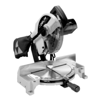
ADJUSTING POINTER
If it becomes necessary to adjust the pointer (A) Fig. 14,
loosen screw (B), adjust the pointer and tighten screw
(B).
Fig. 14
A
B
Fig. 15
Fig. 16
A
A
B
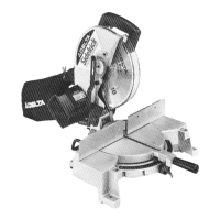
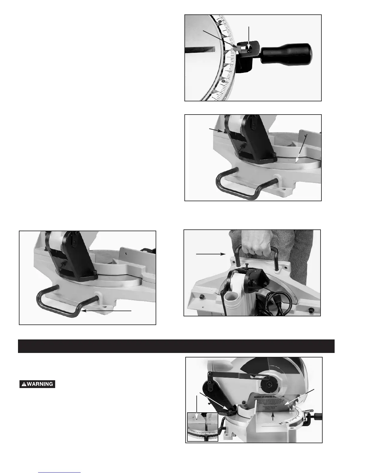
REAR SUPPORT/CARRYING
HANDLE
A rear support bar (A) Fig. 16 is provided to prevent the
miter saw from tipping to the rear when the cutterhead
is returned to the up position. For maximum support,
the bar (A) should be pulled out as far as possible.
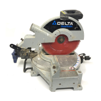
The support bar (A) Figs. 16 and 17 can also be used as
a carrying handle.
LOCKING CUTTERHEAD IN THE
DOWN POSITION
When transporting the miter saw, the cutterhead should
always be locked in the down position. Lower the
cutting arm (A) Fig. 15, and push in plunger (B) until
other end of plunger (B) engages with hole in cutting
arm.
IMPORTANT: Carrying the machine by the switch
handle will cause misalignment. Always lift the machine
by the base or rear support/carrying handle (A) Fig. 16
and 17.
Fig. 18
A
C
B
A
ADJUSTMENTS
Disconnect machine from power source.
 Loading...