EasyManuals Logo
Home>Delta>Network Hardware>R2-EC 004 Series

Delta R2-EC 004 Series User Manual

Delta R2-EC 004 Series
67 pages
To Next Page IconTo Next Page
To Previous Page IconTo Previous Page
Page #27 background imageLoading...
Page #27 background image
Wiring and Installation R2-ECx004 User Manual
3-2
3
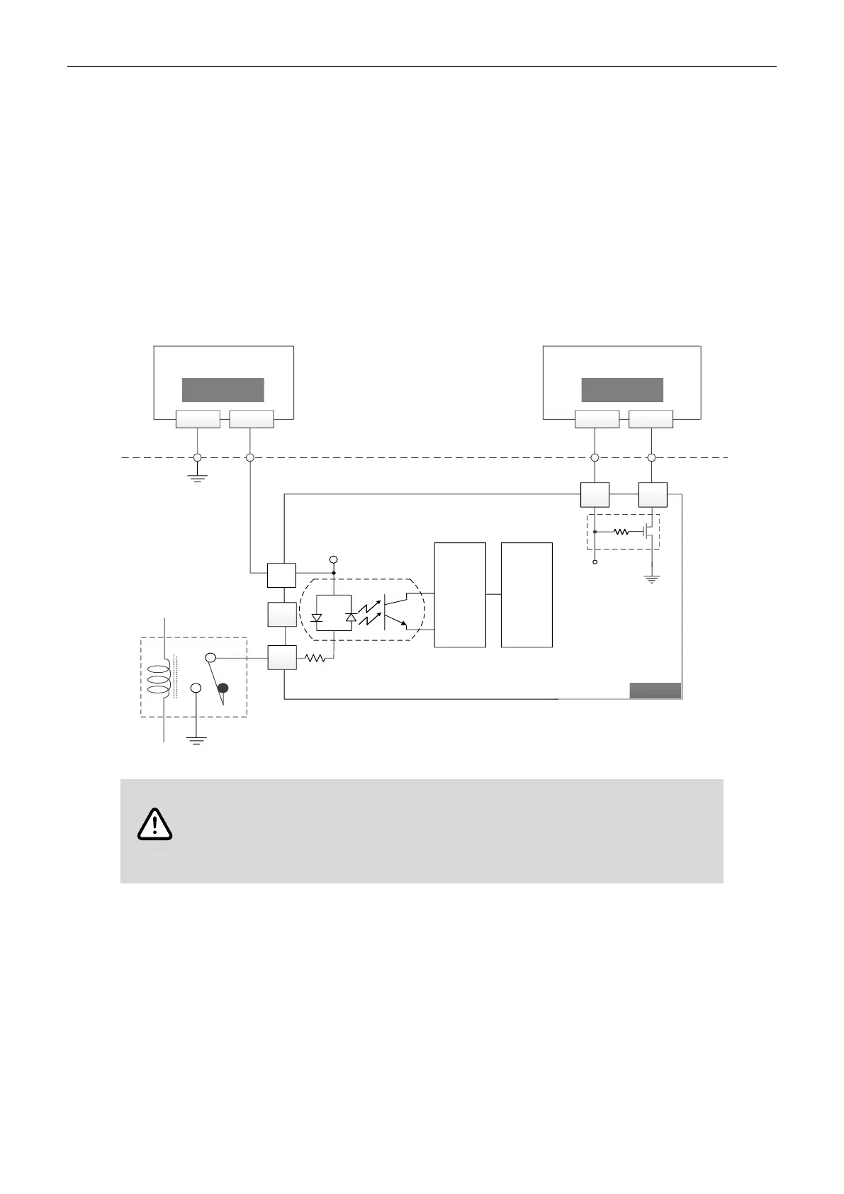
3.1 Input port wiring example
Connect NPN (SINK) type load to R2-ECx004 input ports
The IO power (IO_24V / IOGND) and module power (24VPWR / PWR_GND) should be two
independent power circuits.
The following figure illustrates a single input point (X15). The structure is the same for the other
15 input points (X01 - X14). The rated voltage is 24 V
DC
for the input port and module power
port. Do not use a power supply exceeding 28.8 V
DC
or an AC power supply to avoid damaging
the module circuit.
24V
GND
IOGND
Internal circuit
S/S
X00
Relay
IO_24V
N.O
Controller
X15
LPF: low-pass filter
SINK
N.C
Module power supply
24 VDC
24V 0V
IO power supply
24 VDC
0V 24V
IOGND
24VPWR
PWR_GND
RVP
RVP: reverse voltage protection
LPF
WARNING
Follow these instructions for power supply and wiring to prevent any danger.
Use two independent 24 V
DC
power supplies for the module and the common input /
output points to ensure proper operation.
Use 26 - 18 AWG wires for wiring.

Questions and Answers:

Question and Answer IconNeed help?

Do you have a question about the Delta R2-EC 004 Series and is the answer not in the manual?

Delta R2-EC 004 Series Specifications

General IconGeneral
BrandDelta
ModelR2-EC 004 Series
CategoryNetwork Hardware
LanguageEnglish

Related product manuals