EasyManuals Logo
Home>Delta>Inverter>RPI M50A

Delta RPI M50A User Manual

Delta RPI M50A
228 pages
To Next Page IconTo Next Page
To Previous Page IconTo Previous Page
Page #37 background image
4.5.1. RS-485 Connection
The pin definition of RS-485 is shown in table 4-6. Different RS-485
connection needs different set up of the terminal resistor.
When single inverter is installed, the terminal resistor on its communication
module should be switched ON.
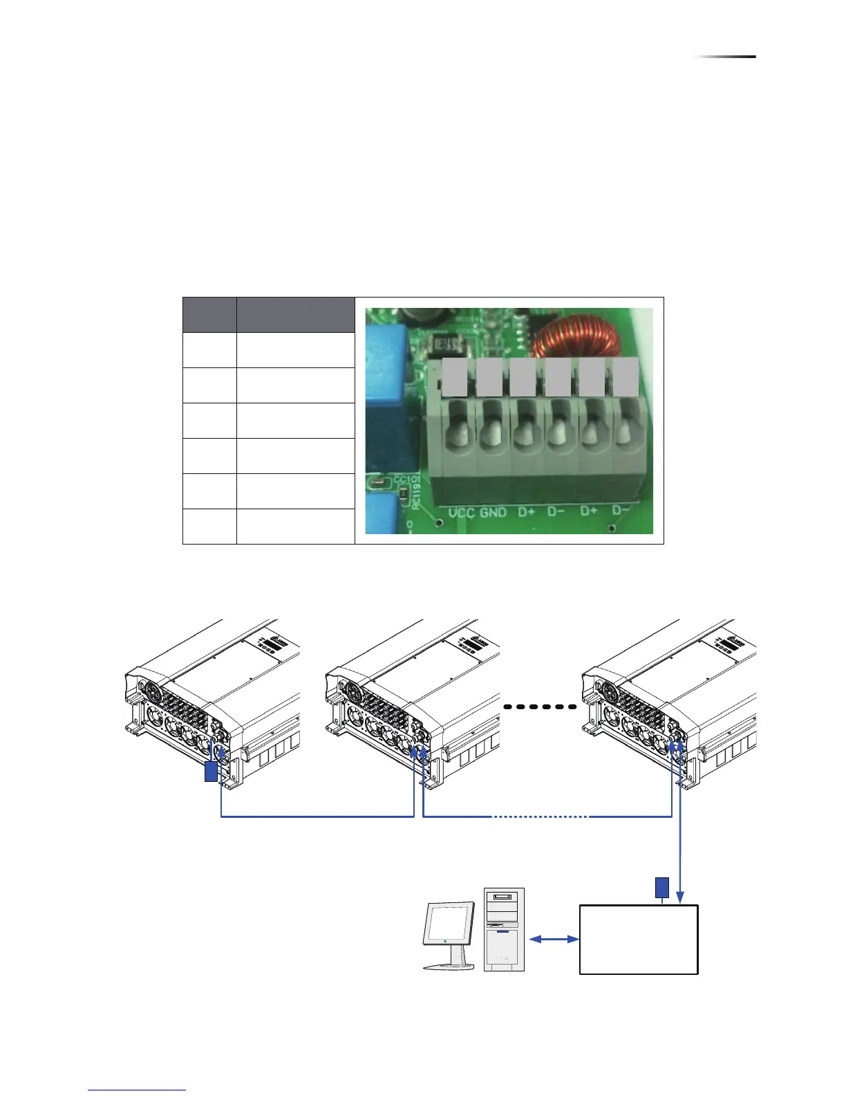
• When multi-inverters in chain as shown in Figure 4-17, only the first and
last inverter’s terminal resistor must be switched ON.
Please refer to table 4-7 for the terminal resister setting.
Pin Function
1 VCC (+12V)
2 GND
3 DATA+
4 DATA-
5 DATA+
6 DATA-
Table 4-6 Definition of RS 485 pin
Figure 4-17 Multi-inverter connection illustration
1 2 3 4 5 6
Data Format:
Baud rate: 9600, 19200 (default), or 38400
Data bits: 8
Stop bit: 1
Parity: N/A
RS485/USB
or
RS485/RS232
Terminal Resistor
120Ω(1/2W)
DATA+ to DATA-
Terminal Resistor
120Ω(1/2W)
DATA+ to DATA-
37
Wiring

Table of Contents

Other manuals for Delta RPI M50A

Questions and Answers:

Question and Answer IconNeed help?

Do you have a question about the Delta RPI M50A and is the answer not in the manual?

Delta RPI M50A Specifications

General IconGeneral
BrandDelta
ModelRPI M50A
CategoryInverter
LanguageEnglish

Related product manuals