Chapter 2 Installation and Wiring_VFD-B Series
Revision 10/2005, BE13, SW V4.08 2-21
If the AC motor drive has a built-in brake chopper (all models of 11kW and below), connect the
external brake resistor to the terminals [
Ѐ
2/B1, B2].
Models of 15kW and above don’t have a built-in brake chopper. Please connect an external optional
brake unit (VFDB-series) and brake resistor. Refer to VFDB series user manual for details.
Connect the terminals [+(P), -(N)] of the brake unit to the AC motor drive terminals [+2(+2/B1), (-)].
The length of wiring should be less than 5m with twisted cable.
When not used, please leave the terminals [+2/B1, -] open.
WARNING!
Short-circuiting [B2] or [-] to [+2/B1] can damage the AC motor drive.
Grounding terminals (
)
Make sure that the leads are connected correctly and the AC drive is properly grounded. (Ground
resistance should not exceed 0.1
Ө
.)
Use ground leads that comply with local regulations and keep them as short as possible.
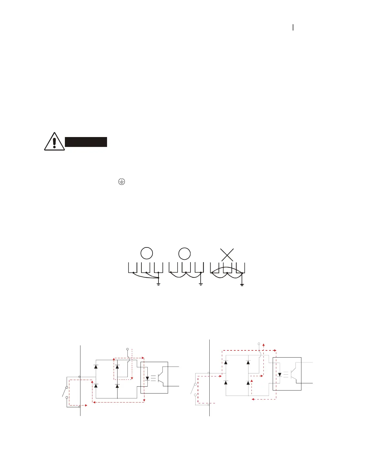
Multiple VFD-B units can be installed in one location. All the units should be grounded directly to a
common ground terminal, as shown in the figure below. Ensure there are no ground loops.
goodexcellent
not allowed
2.4.4 Control Terminals
Circuit diagram for digital inputs (SINK current 16mA.)
+24
SINK Mode
multi-input
terminal
Internal CircuitDCM
+24V
Multi-Input
Terminal
DCM
Internal Circuit
SOURCE Mode
 Loading...