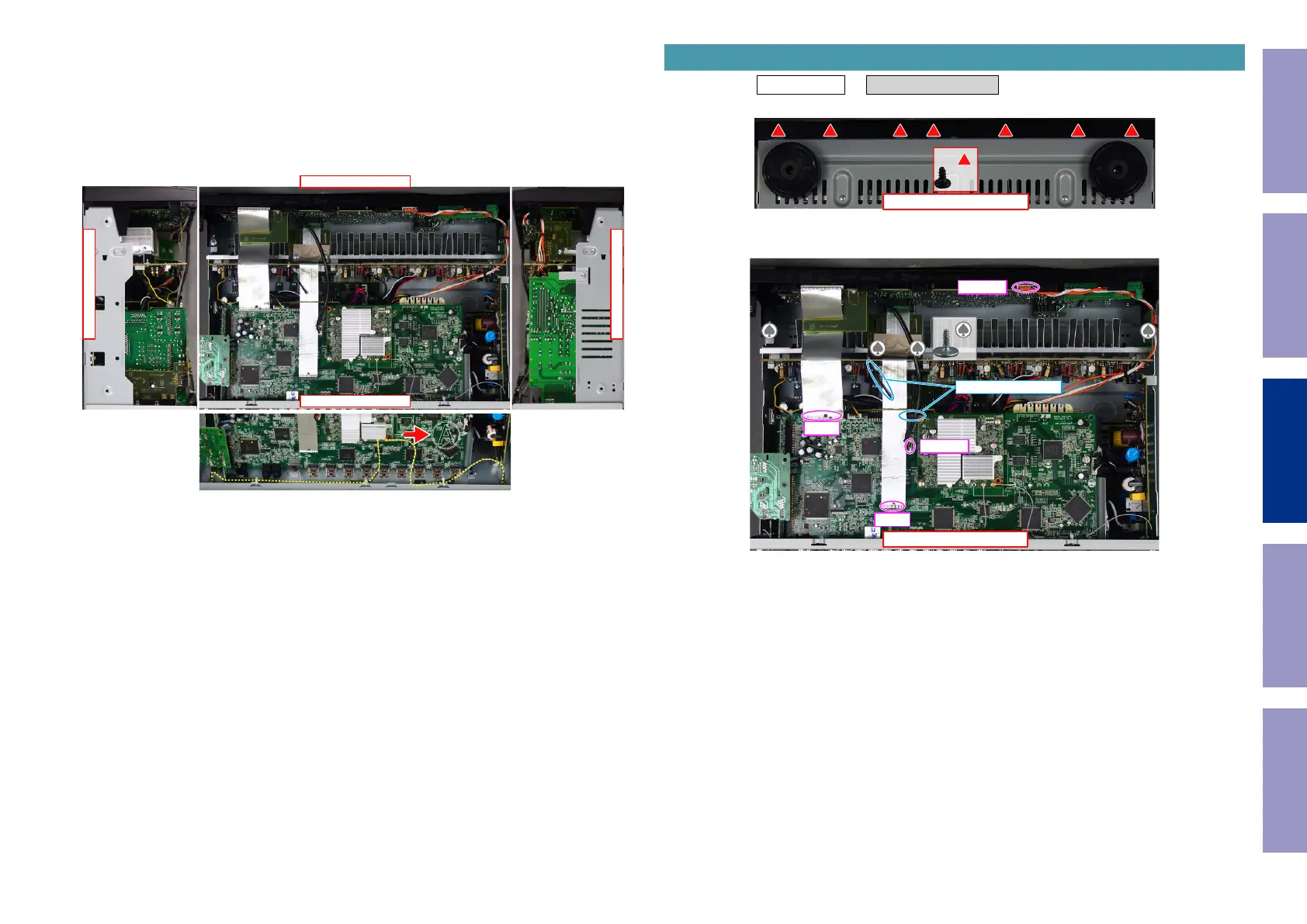
Explanatory Photos for DISASSEMBLY
• For the shooting direction of each photos used in this manual, see the photo below.
• A, B, C and D in the photo below indicate the shooting directions of photos.
• The photographs with no shooting direction indicated were taken from the top of the unit.
• Photos of AVR-X2500H E3 are used in this manual.
The viewpoint of each photograph
(Shooting direction : X) [View from the top]
Attention :
When reinserting the Antenna Cable after it has been disconnected, make sure it is facing the direction
shown in A above.
↓Shooting direction: C↓
↑Shooting direction: D↑
↑Shooting direction: A↑
↓Shooting direction: B↓
�
Proceeding : TOP COVER → FRONT PANEL ASSY
(1) Remove the screws.
(2) Remove the screws. Remove the CORD HOLDER and connectors. Remove the FFC.
1. FRONT PANEL ASSY
View from the bottom
x7
↑Shooting direction: A↑
x4
CP4400
FFC
FFC
N1008
CORD HOLDER
Before Servicing
This Unit
Electrical Mechanical Repair Information Updating
72
 Loading...