 Loading...
Do you have a question about the Denon HOME 350 and is the answer not in the manual?
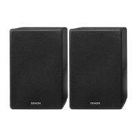
| Product color | Black |
|---|---|
| Volume control | Touch |
| Recommended usage | Tablet / Smartphone |
| Remote control type | Wireless |
| Multi-Room Streaming (MRS) support | Yes |
| Speaker type | - |
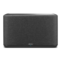
| Woofer diameter | 165 mm |
| Tweeter diameter | 19 mm |
| Number of drivers | 6 |
| Speaker placement | Tabletop/bookshelf |
| Audio output channels | 2.0 channels |
| Mid-range driver diameter | 50 mm |
| Number of mid-range drivers | 2 |
| RMS rated power | - W |
| Amplifier class | D |
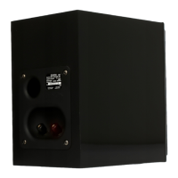
| Connectivity technology | Wired & Wireless |
| Ethernet LAN (RJ-45) ports | 1 |
| Cables included | AC |
| Package depth | 248 mm |
| Package width | 468 mm |
| Package height | 338 mm |
| Package weight | 8500 g |
| AC input voltage | 100 - 240 V |
| AC input frequency | 50 - 60 Hz |
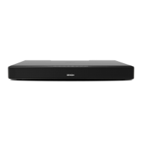
| Depth | 180 mm |
|---|---|
| Width | 380 mm |
| Height | 225 mm |
| Weight | 6300 g |
General safety instructions and warnings for servicing the unit.
Important notes regarding schematic diagram conventions and symbols.
Guidelines for safely handling sensitive electronic components.
Instructions on how to access and search the online parts catalog.
Information on the organization and meaning of the product serial number.
Steps to perform after servicing to ensure proper unit function.
Detailed circuit diagrams for various modules and functions of the unit.
Layout diagrams of the main printed circuit boards for reference.
High-level overview of the unit's internal architecture and component connections.
Flowchart illustrating the power distribution and voltage regulation within the unit.
Diagram showing the interconnections between different PCBs and components.
List and diagrams of major semiconductor components used in the unit.
Step-by-step procedures and flowcharts for disassembling the unit.
Illustrated breakdown of the unit's components for identification during disassembly.
Details on gasket placement for maintaining air leak prevention.
Diagrams illustrating the protective packaging components for shipping.
Guides for diagnosing and resolving common operational issues and errors.
Procedures for entering and utilizing special operational modes for service.
Explanation of LED indicators and their meaning during various operations.
Steps required after replacing key components like U-COM or flash ROM.
Methods and requirements for updating the unit's firmware.
Specific workflow for updating firmware after replacing the network module.