36
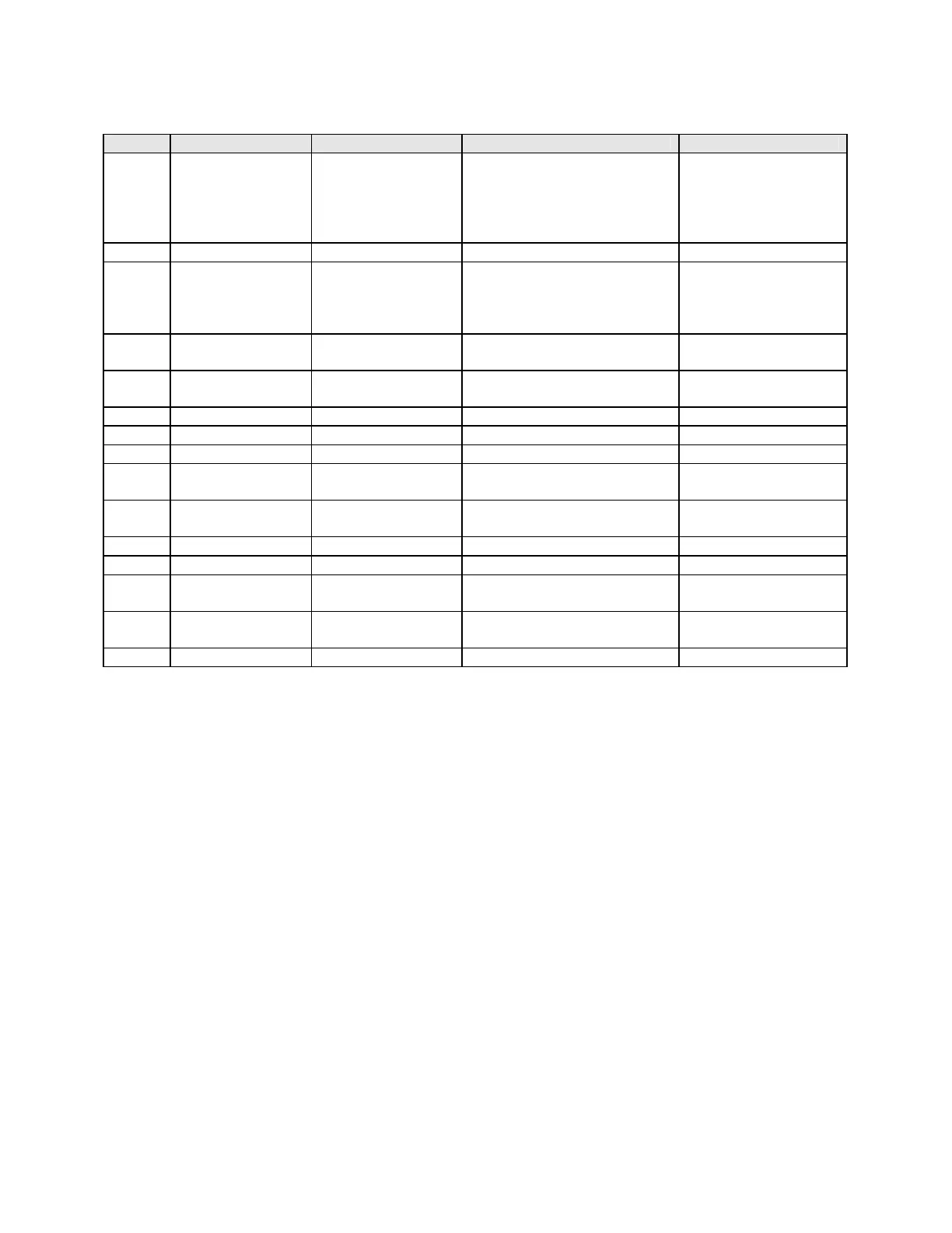
Table 6-1 Alarm Mode Parameters
STEP DESCRIPTION DISPLAY CODE AVAILABLE SETTINGS FACTORY SETTING
1 Alarm 1 Type ALA1 P-hi=Proc High
nonE=No Alarm
bAnd=Band
dE=Deviation
P-Lo=Proc Low
P_hi
2 Alarm 2 Type ALA2 Same selection as ALA1 P_hi
3 Alarm Inhibit Inhi nonE=No Inhibit
ALA1=Alarm1 Inhibited
ALA2=Alarm2 Inhibited
both=Both Inhibited
nonE
4a Process High
Alarm 1
PHA1
2
± Span Span Max.
4b Process Low
Alarm 1
PLA1
2
± Span Span Min.
4c Band Alarm 1 bAL1
2
0 to Span 5
4d Deviation Alarm 1 dAL1
2
± Span 5
5 Alarm Hysteresis Ahy1
2
1 LSD to 10% of span 1 LSD
6a Process High
Alarm 2
PHA2
2
± Span Span Max
6b Process Low
Alarm 2
PLA2
2
± Span Span Min.
6c Band Alarm 2 bAL2
2
0 to Span 5
6d Deviation Alarm 2 dAL2
2
± Span 5
7 Alarm 2
Hysteresis
AHy2
2
1 LSD to 10% of span 1 LSD
8 Loop Alarm
Enable
LAEn diS = Disabled
EnAb = Enabled
diS
9 Loop Alarm Time LAti
1
1 sec to 99 mins. 59 secs. 99 mins. 59 secs.
1 Only displayed when loop alarm is enabled and ON/OFF control is selected.
2 Only displayed when alarm type is other than none. Only type selected is displayed.
 Loading...