52
3. Enter Calibration Mode (Section 9.1). The upper display will then show Input
Type Number, in the form:
iP_I
and the lower display will show:
CAL
Using the UP/DOWN keys, change the input type number as required (see Table
9-1).
NOTE: If required, only one input type may be calibrated. Exception: If it is
required to calibrate the thermocouple input (Input Type 5), it is necessary first to
calibrate the DC 0 - 50 mV input (Input Type 1).
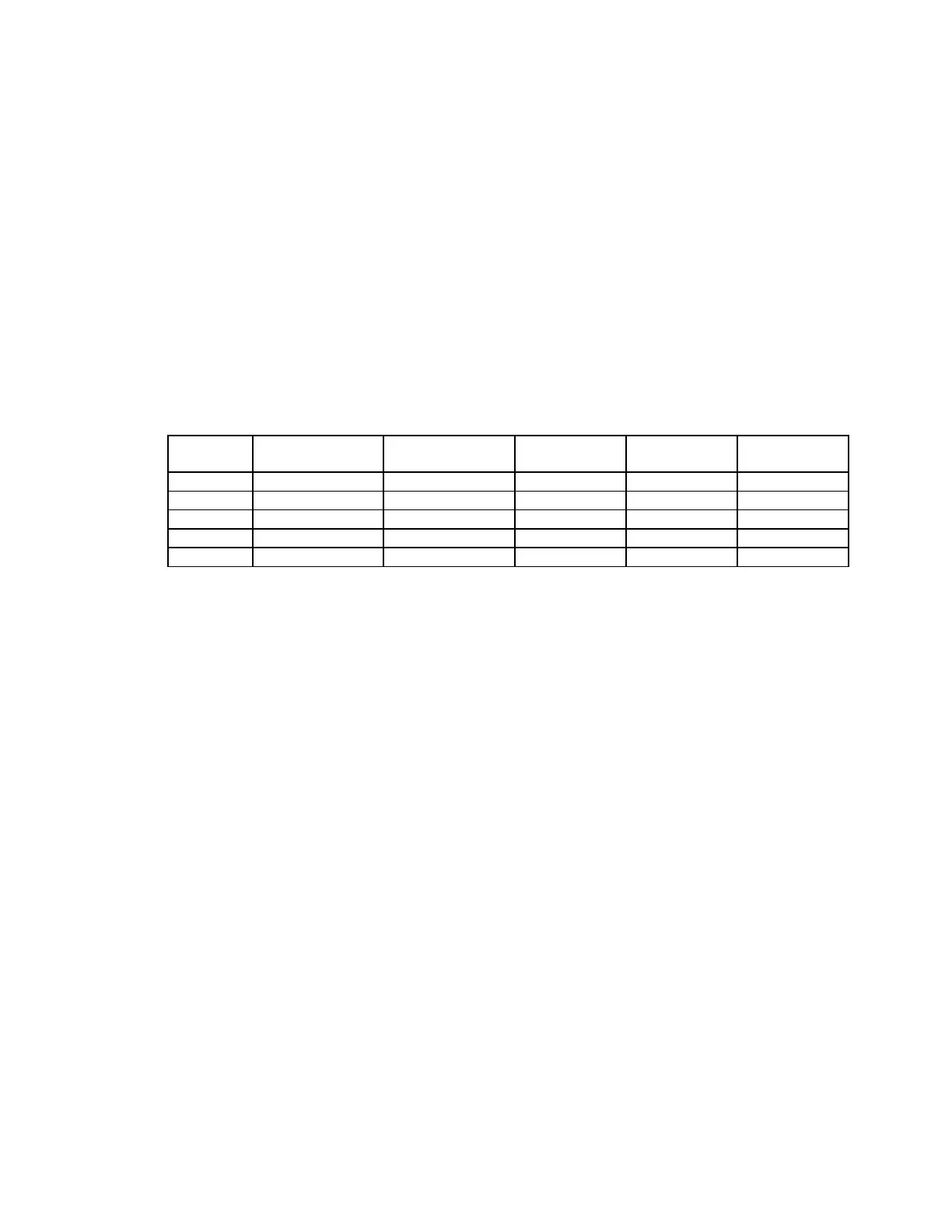
Table 9-1 Universal Input Type Selection
Input
Type No.
Input Type Calibration Input Link Jumper
1
Link Jumper
2
Link Jumper
3
1 0 - 50 mVDC 50 mVDC Parked Parked Parked
2 0 - 10 VDC 10 VDC Fitted Parked Parked
3 0 - 20 mADC 20 mADC Parked Fitted Parked
4 3-wire RTD 200 ohm Parked Parked Parked
5 Thermocouple 0° C “K” Parked Parked Fitted
4. Press the AUTO/MANUAL key to change the upper display to show:
_ _ _ _
After a few seconds, the upper display will either (a) return to the initial Input
Type Number display if calibration was successful, or (b) display:
FAIL
In the latter case, the link jumpers and wiring should be checked.
5. To calibrate all inputs, repeat Steps 1 to 4 for each of the other input types (see
Table 9-1) until all desired input types have been successfully calibrated.
The universal input calibration procedure is now complete. Power down the
control and ensure the jumpers on the CPU PCB are in the correct position
according to input type, and according to Figure A-2.
 Loading...