7
ENGLISH
DO NOT use under wet conditions or in the presence of flammable liquids
orgases.
These hammers are professional powertools.
DO NOT let children come into contact with thetool. Supervision is
required when inexperienced operators use thistool.
• Young children and theinfirm. This appliance is not intended for use
by young children or infirm persons withoutsupervision.
• This product is not intended for use by persons (including children)
suffering from diminished physical, sensory or mental abilities; lack of
experience, knowledge or skills unless they are supervised by a person
responsible for theirsafety. Children should never be left alone with
thisproduct.
Soft Start Feature
D25601, D25604, D25831
The soft start feature allows the tool to accelerate slowly, thus preventing
the drill bit from walking off the intended hole position whenstarting.
The soft start feature also reduces the immediate torque reaction
transmitted to the gearing and the operator if the hammer is started with
the drill bit in an existinghole.
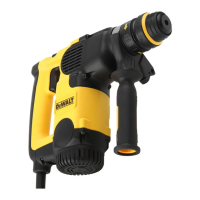
Electronic Speed and Impact Control (Fig. A, C)
D25601, D25604, D25831
The electronic speed and impact control
7
offers the following advantages:
- use of smaller accessories without risk of breakage;
- minimised break-out when chiselling or drilling in soft or
brittlematerials;
- optimal tool control for precisechiselling.
Torque Limiting Clutch
WARNING: The user must always maintain a firm grip on the tool
when inoperation.
The torque limiting clutch reduces the maximum torque reaction
transmitted to the operator in case of jamming of a drillbit. This feature also
prevents the gearing and electric motor fromstalling.
Anti-Rotation System (Fig.C)
D25604
Ant-Rotation System offers increased user comfort and safety through an
on-board, anti-rotation technology capable of detecting if the user loses
control of thehammer. When a jam is detected, the torque and speed are
reducedinstantly. This feature prevents self rotation of the tool reducing the
occurrence of wristinjuries.
Service Indicator LEDs (Fig. A, C)
D25601, D25604, D25831
The yellow brushwear indicator LED
17
lights up when the carbon brushes
are nearly worn out to indicate that the tool needs servicing within the next
8 hours ofuse.
D25604
The red service indicator LED
16
lights up if the lock-on button
2
is
used in any mode except the chippingmode. On models fitted with
Ultimate Torque Control (UTC), the red LED indicator
16
lights up if the
anti-rotational device isactivated. The red indicator starts to flash if there
is a fault with the tool or the brushes have completely worn out (refer to
Brushes under Maintenance).
D25601, D25831
The red service indicator LED
16
lights up if there is a fault with
the tool or the brushes have completely worn out (refer to Brushes
underMaintenance).
Under exposure of certain electromagnetic phenomena(fast transients) it
can happen that the machine will reduce speed down to zero RPM. This
will be shown by flashing of the service indicator. To undo this mode the
machine needs to be switched off and on one time. After cycling the trigger
switch the machine is back in normal operating mode.
Fully Vibration-Dampened Main Handle (Fig. A)
D25601, D25604, D25831
The dampers in the main handle
4
absorb the vibrations transmitted to
theuser. This improves user comfort during theoperation.
ASSEMBLY AND ADJUSTMENTS
WARNING: To reduce the risk of serious personal injury,
turn tool off and disconnect tool from power source before
making any adjustments or removing/installing attachments
oraccessories. An accidental start-up can causeinjury.
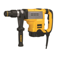
Fitting the Side Handle (Fig. B)
The side handle
3
clamps to the mounting area
12
of the gear case and
may be rotated 360˚ to permit right- or left-hand use. The side handle
must be tightened sufficiently to resist the twisting action of the tool if the
accessory binds or stalls. Be sure to grip the side handle at the far end to
control the tool during astall.
To loosen side handle, rotatecounterclockwise.
Inserting and Removing SDS Max Accessories
(Fig. A, D)
This machine uses SDS Max bits and chisels (refer to the inset in FigureD for
a cross-section of an SDS Max bit shank).
1. Clean the bitshank.
2. Pull back the locking sleeve
11
and insert the bitshank.
3. Turn the bit slightly until the sleeve snaps intoposition.
4. Pull on the bit, to check if it is properlylocked. The hammering function
requires the bit to be able to move axially several centimetres when
locked in the toolholder.
5. To remove a bit pull back the tool holder locking sleeve/collar
11
and
pull the bit out of the tool holder
10
.
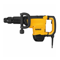
Selecting the Operating Mode (Fig. A)
Hammerdrilling:
D25501, D25601, D25604
for concrete, brick, stone and masonry drillingoperations.
Hammering only:
D25501, D25601, D25604, D25831
for chiselling and demolitionapplications. In this mode the tool
can also be used as a lever to free a jammed drillbit.
1. To select the operating mode, rotate the mode selector switch
6
until
it points to the symbol of the requiredmode.
It may be neccessary to twist the tool holder
10
slightly to allow the
mode selector switch
6
to pass the position.
2. Check that the mode selector switch
6
is locked inplace.
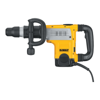
Indexing the Chisel Position (Fig. E)
The chisel can be indexed and locked into 18 differentpositions.
1. Rotate the mode selector switch
6
until it points towards the
position.
2. Rotate the chisel in the desiredposition.
3. Set the mode selector switch
6
to the “hammering only”position.
4. Twist the chisel until it locks inposition.
Setting the Electronic Speed and Impact Control Dial
(Fig. A, C)
D25601, D25604, D25831
Turn the dial
7
to the desiredlevel. Turn the dial upwards for higher
speed and downwards for lowerspeed. The required setting is a matter of
experience, e.g.
• when chiselling or drilling in soft, brittle materials or when minimum
break-out is required, set the dial to a low setting;
 Loading...