ENGLISH
6
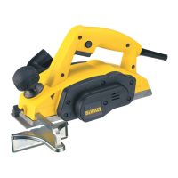
holes. If mounting the planer with nails or screws, use the
smaller holes. It is not necessary to use both sets ofholes.
Fig. E
5
Always mount your planer firmly to a secure surface to
prevent movement. To enhance the tool’s portability, it can
be mounted to a piece of 1/2" (12.7mm) or thicker plywood
which can then be clamped to your work support or moved
to other work areas andreclamped.
NOTE: If you elect to mount your planer to a piece of
plywood, make sure that the mounting screws don’t
protrude from the bottom of the wood. The plywood must
sit flush on the worksupport.
CAUTION: The mounting surface should not be
warped or otherwiseuneven.
ASSEMBLY
WARNING: To reduce the risk of serious personal
injury, turn tool off and disconnect tool from
power source before making any adjustments or
removing/installing attachments or accessories.
An accidental start-up can causeinjury.
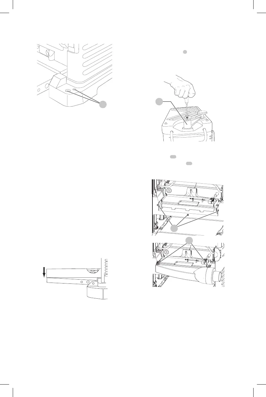
Table Extensions (Fig. F)
Before using your planer, fold down the table extensions
in the front and back of the tool. After extended use, the
table extensions may be slightly out of level. See Leveling
the Table Extensions in the Maintenance section of
thismanual.
Fig. F
NOTE: The outside edges of the extension tables are
level with the base while the inside edges (closest to the
cutterhead) are below the edge of the base. This is set at the
factory to reduce unnecessary friction between the material
and the table while providing adequate support at the two
points (those farthest from the cutterhead) on the tables
that are integral to snipeprevention.
Depth Adjustment Crank Handle
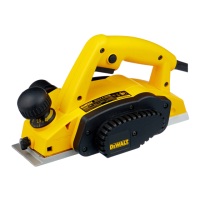
To Attach the Depth Adjustment Crank
Handle (Fig. G)
1. Insert the crank handle
6
over theshaft.
2. Secure the crank handle in place with the star screw and
T-wrenchprovided.
Fig. G
6
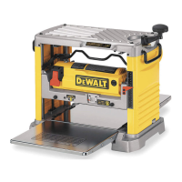
Dust Hood Installation (Fig. H)
1. Remove screws
23
, save thesescrews.
2. Slide the dust hood clips
24
into place on front of the
tool tray and rotate dust hood intoplace.
Fig. H
23
24
3. Align holes in dust hood with holes in tool tray and
motor housing, secure with screws removedearlier.
NOTE: Tighten the bottom screw first and then the two
sidescrews.
4. Attach dust hood to a dust collector. Refer to dust
collector owner's manual for correct procedure and
safetyinformation.
NOTE: The dust hood is to be attached only when
connecting the planer to a dust collection system.
Remove the dust hood if the planer is to be used
alone to allow for the chips to fall freely out of the
planerexhaust.
NOTE: Do not connect a vacuum cleaner or shop vac to the
dust hood. The capacity of most vacs does not support the
 Loading...