ENGLISH
7
volume of chips ejected during planing. The vacuum hose
may clog, stopping the flow ofchips.
Depth Adjustment (Fig. I)
The depth adjustment scale
10
indicates the finished
thickness of your workpiece. One rotation of the depth
adjustment crank is equal to 1/16" (1.6mm); half a rotation
is equal to 1/32" (0.8mm),etc.
Fig. I
10
To Set the Finished Thickness (Fig. D)
1. Raise head lock lever
9
to unlock the cutterhead. This
allows the cutterhead to beadjusted.
2. Adjust the thickness. Turn the depth adjustment
handle
6
clockwise to lower the cutterhead. Turn the
handle counterclockwise to raise the cutterhead. One
full rotation of the handle moves the cutterhead 1/16"
(1.6mm).
3. Depress the head lock lever to re-lock beforeplaning.
NOTE: Do not attempt to adjust the carriage height while
the carriage lock is engaged. You may damage themachine.
Fine Adjustments
The depth adjustment handle allows for fine adjustments,
from 1/64" (0.4mm) to 1/16" (1.6mm).
Fine adjustments are ideal for “shaving” small amounts
from your material. For example, if your planed workpiece
measures 3-1/16" (77.8mm) thick, but should be 3"
(76.2mm) thick, adjust your planer to remove the excess
1/16" (1.6mm) as follows:
1. Plane and measure your workpiece. In this example, the
starting thickness is 3-1/16" (77.8mm).
2. Turn the circular label on the depth adjustment handle
until the “0” mark aligns with the arrow on the top
of the tool. Do not make any other adjustments to
theplaner.
3. Turn the depth adjustment handle clockwise until the
1/16" (1.6mm) mark aligns with thearrow.
4. Plane your workpiece. The final thickness should be 3"
(76.2mm).
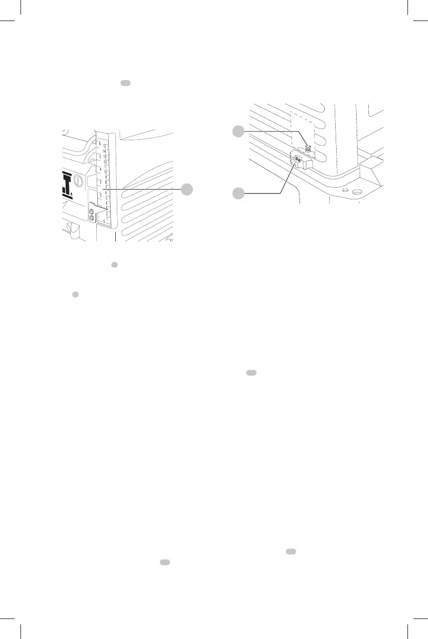
Turret Stop (Fig. D, J)
Your planer is equipped with a turret stop
13
, shown in
FigureJ, for repetitive planing of pre-set depths. Stops are
set at 0", 1/4" (6.4 mm), 1/2"12.7 mm) and 3/4" (19.0 mm).
Use the 0" setting when planing between 1/8" (3.2 mm) and
1/4" (6.4mm).
To Set a Planing Depth
1. Be sure the carriage is set above 1-1/4" (31.8 mm)
before trying to set the turretstop.
2. Turn the turret stop until the desired measurement
shows (Fig.J).
Fig. J
14
13
3. Unlock the head lock lever (Fig.D). Turn the depth
adjustment crank, lowering the carriage by the desired
increments, until it contacts the turretstop.
NOTE: DO NOT USE FORCE TO CRANK THE CARRIAGE
BELOW THE LEVEL THAT THE TURRET STOP INDICATES.
PERMANENT DAMAGE TO THE HEIGHT ADJUST MENT
SYSTEM ON YOUR PLANER WILLRESULT.
NOTE: The 3/4" (19.0 mm) turret stop can be adjusted for
other planing thicknesses. Adjusting the 3/4" (19.0 mm)
turret stop does not affect the other turret stopsettings.
To Adjust the 3/4" (19 mm) Stop for
Other Thicknesses
1. Unlock the head lock lever (Fig.D) and turn the
adjustment handle counterclockwise to raise
thecutterhead
2. From the back of the tool, locate the turret adjustment
bolt
14
shown in FigureJ. This bolt is set for a 3/4"
(19.0mm) depth of cut at the factory. Adjust the bolt up
or down to reach the desired planingdepth.
3. Turn the depth adjustment crank, lowering the
carriage by the desired increments, until it contacts the
turretstop.
Calibrating the Depth Adjustment Scale
The depth adjustment scale on your planer is set at the
factory. However, with extended use, the depth adjustment
scale could show an incorrectmeasurement.
To Check the Depth Adjustment Scale
(Fig. K)
1. Plane a piece of wood, noting the measurement on the
depth adjustmentscale.
2. Measure the finished thickness of theworkpiece.
3. If the thickness of the workpiece does not match the
reading on the depth adjustment scale, loosen the two
cross head screws
18
shown in FigureK.
 Loading...