EasyManuals Logo
Home>Digital-Ally>DVR>DVM-250 Plus

Digital-Ally DVM-250 Plus User Manual

Default Icon
27 pages
To Next Page IconTo Next Page
To Previous Page IconTo Previous Page
Page #16 background imageLoading...
Page #16 background image
VuLink Operation & Installation Guide 860-00198-00 REV A
Digital Ally, Inc. | Model-Specific Wiring Diagrams
4-1
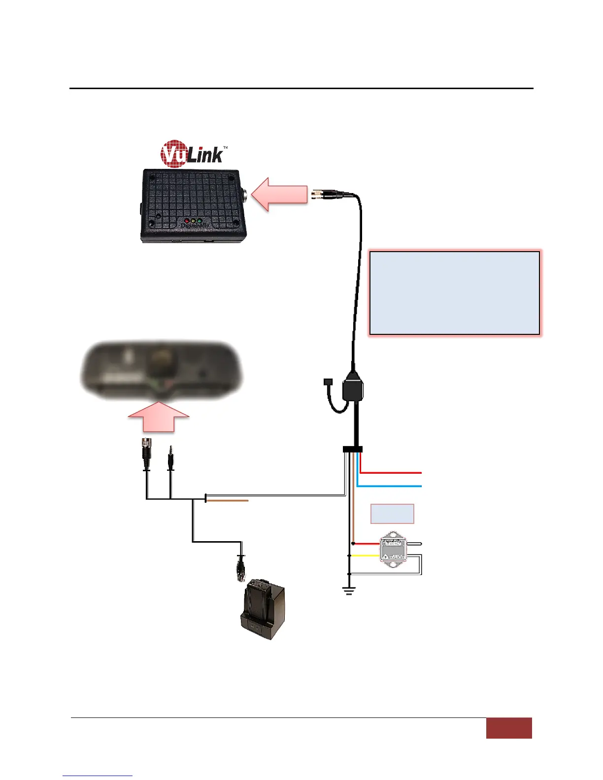
Section - 4: Model-Specific Wiring Diagrams
DVM-100 / DVM-400
VuLink Base Cable
008-01456-00
RED = +12VDC Battery
BLUE = +12VDC Ignition
BLACK = Chassis Ground
WHITE = Emergency Light Input
WHITE = Tie to ground
Relay
(see
belo
w)
DWM800
Sensor Cable
Connect WHITE wire from
VuLink Base Cable to WHITE
wire of DWM800 sensor cable
VuLink Relay Wiring
WHITE = connect to Emergency lights
WHITE = connect to chassis ground
YELLOW = connect to chassis ground
RED = connect to BROWN wire on
VuLink base cable
NC

Other manuals for Digital-Ally DVM-250 Plus

Questions and Answers:

Question and Answer IconNeed help?

Do you have a question about the Digital-Ally DVM-250 Plus and is the answer not in the manual?

Digital-Ally DVM-250 Plus Specifications

General IconGeneral
BrandDigital-Ally
ModelDVM-250 Plus
CategoryDVR
LanguageEnglish

Related product manuals