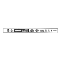
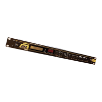
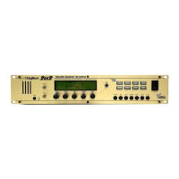
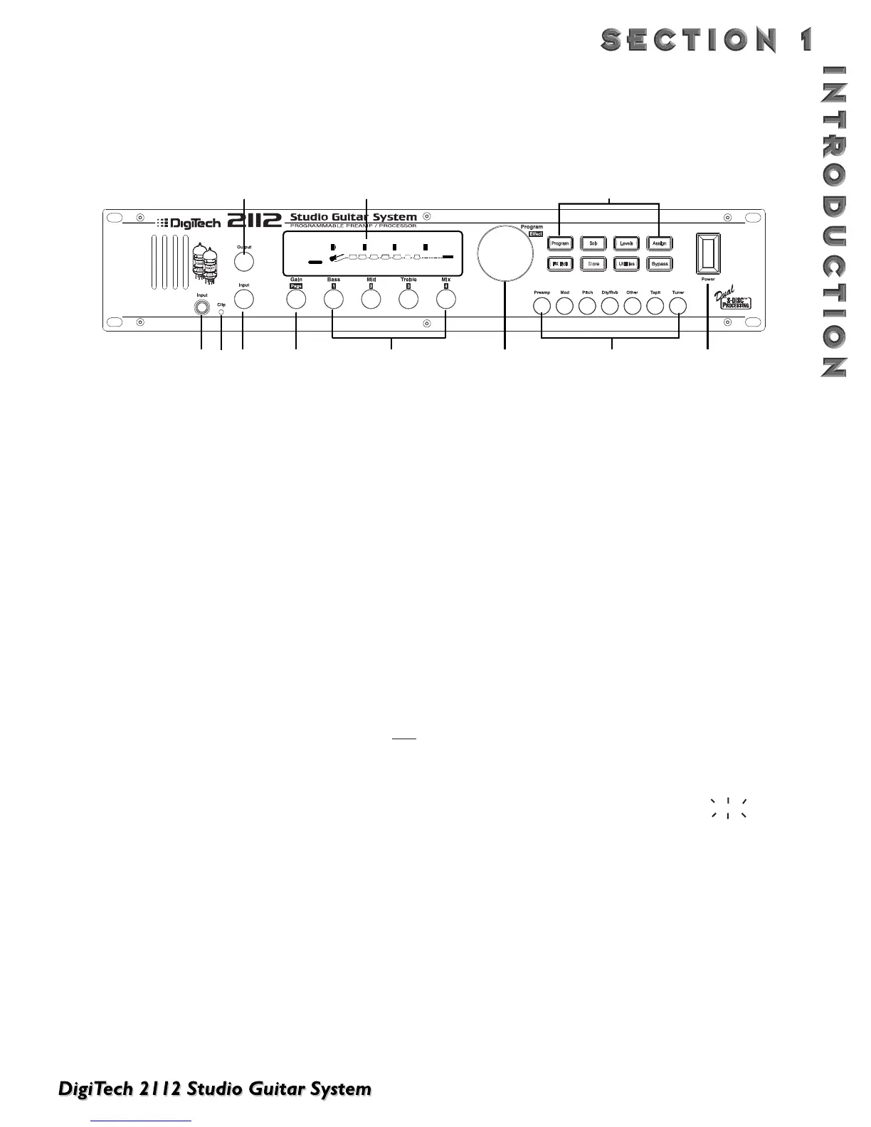
1) Output Level Knob - Controls the overall output
level of the 2112.
2) Display - This large custom display is where you get
most of the information you need to move around
the operating system.The display has several sec-
tions:
2a) Program Number Indicator - Three large dig-
its in the upper left corner of the display indicate
which Program is currently selected.
2b) Factory / User Indicators - Directly below the
Program number, the Factory and User Program
icons indicate whether the current program resides
in either a Factory or User Bank.
2c) Bank / Page Indicators - Located in the bot-
tom left corner of the display, the Bank/Page indi-
cators display:
• the Bank number in which the current program
resides in Program Mode. (This is displayed onl
y
when the Control One is connected).
• the Page which is currently selected in various
Edit modes.
2d) Information Line - Row of 24 characters in the
top line of the display gives more detailed infor-
mation about specific functions and items, and
contains things like Program names, Parameter
names, and Utility or auxiliary information.
2e) Parameter Data Sections - Immediately below
the Information line are four Parameter Data sec-
tions. They correspond with the <1> through
<4> knobs on the front panel. Each section dis-
plays the current value of the indicated
Parameter.
A CC indicator in each group tells whether the
indicated Parameter is set up to be continuously
controlled. When a parameter has been modified,
the Changed icon will appear under the parameter
that has been modified and the <Store> button will
light to indicate a change has been made to the
Program, but not stored.
2f) Input Level / Clip Meters - An Input Level and
Clip meter is located in the bottom center of the
display. This meter shows the Preamp level, and
uses a peak detector action to display the highest
levels at the input. The Clip indicator at the end
of the meter, indicates if the the input signal is
being clipped at the analog input section (pre-digi-
tal) or in the digital effects domain.
2g) Effect Routing Matrix - The Effect Routing
Matrix shows the signal flow of the currently
selected Program. This matrix includes boxes that
represent each effect module along with lines that
indicate how those effects are connected to
inputs, outputs and each other. If an effect module
is bypassed, a line appears through that module's
box in the Matrix.
When in FX Edit mode, the box that represents
the currently selected effect module will flash.
3) Input Jack - Plug Guitar in here.
4) Clip LED -The Clip LED Indicates that the input sig-
nal is causing input stage clipping in the 2112.
5) Input Level Knob - Controls the input level to the
2112.
6) Gain/Page Knob - Controls the Distortion Gain
Parameter either locally or globally. Selection of
either Global or Local mode can be found on Page
11 of the Utilities Menu.When the 2112 is in Edit
mode, the Page knob is used to scroll through the
pages of the selected Module.
A QUICK TOUR OF THE 2112
THE FRONT PANEL
 Loading...