33
Delay D Sets the length of time before hearing Delay Group C and Delay Group D. Ranges from 0
to 120 milliseconds.
Out A - D Controls the output level of the Delay Groups. Ranges from Off to 100%.
Bal A - D Controls the left/right balance of the Delay Groups. Ranges from -99 to 99.
Shape Selects the shape of the output levels for the delay group taps. Shape selections are: Flat,
Peak, Decreasing, Increasing, Shelf, and Reverse Shelf.
Spread Controls the width of the effect’s stereo imaging. Ranges from 1 to 10.
FB: Dly Sets the amount of time before the delay is fedback in. Ranges from 0 to 170 ms.
Amount Sets how much delay is fedback into the signal. Ranges from Off to 50%.
Out L - R Adjusts the overall level of the left/right side of the reverb. Ranges from Off to 100%.
Prim Out L Adjusts the overall level of the left side of the Primary reverb. Ranges from Off to 100%.
Prim Out R Adjusts the overall level of the right side of the Primary reverb. Ranges from Off to 100%.
Secd Out L Adjusts the overall level of left side of the Secondary reverb. Ranges from Off to 100%.
Secd Out R Adjusts the overall level of the right side of the Secondary reverb. Ranges from Off to
100%.
CHORUSES AND FLANGERS
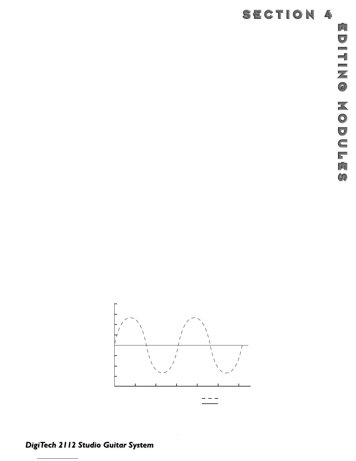
Both choruses and flangers use a Low Frequency Oscillator (LFO) to produce their rich, swirling effects.When you
change the speed and depth Parameters of modulation effects, you're actually controlling the frequency and amplitude
of the LFO.These settings determine the rate and intensity of the modulation effect.
In general, here's how choruses and flangers work: after entering the Module, the source signal is split into two
paths. One is allowed to pass through the Module unaltered, while the other is delayed and pitch modulated.The
modified sound is then sent to the output, along with the original. In Fig. 4-1 below, a sine wave is used to modu-
late the pitch of the split sound source.
The Dual Chorus creates two different pitch “voices”, while the Octal Chorus creates eight voices for extremely
full, rich sounds .
Figure 4-1 Modulation Example
 Loading...