6
IP1897EN • 2012-03-22
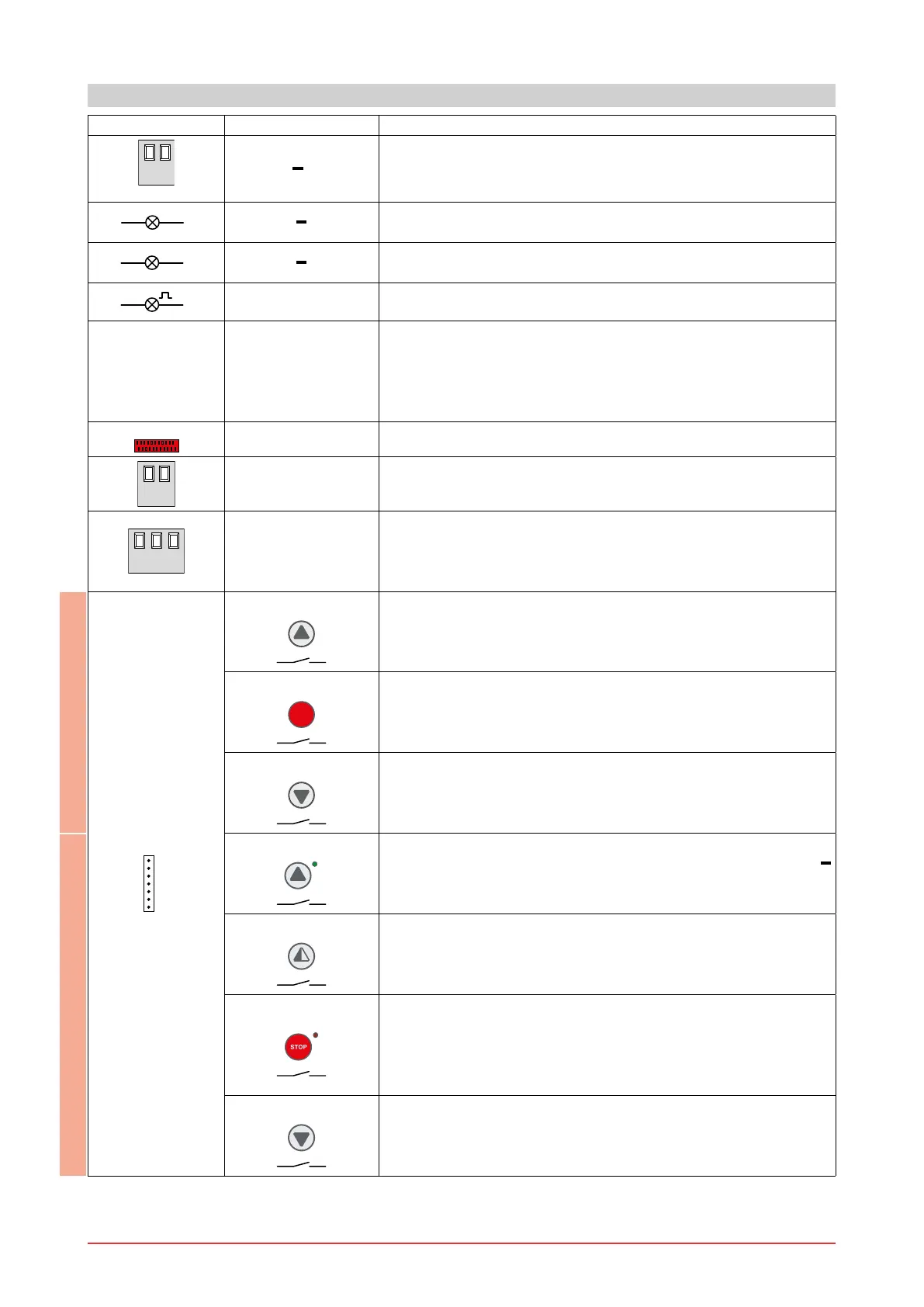
Output Value - Accessories Description
24 V 0.5 A
Accessories power supply. Power supply output for external ac-
cessories, including automation status lamp.
1
11
24 V
3 W
Open automation lamp. The light switches o when the automa-
tion is closed.
1
12
24 V
3 W
Closed automation lamp. The light switches o when the auto-
mation is open.
0
14
LAMPH
Flashing light. Activated during opening and closing operations.
AUX1
AUX2
The control panel has two housings for plug-in cards such as a
radio receiver type, magnetic loops, etc.
Plug-in card operating is selected using DIP1.
WARNING: the plug-in cards must be inserted and removed with
the power supply disconnected.
DO NOT USE
+LK
-
DO NOT USE
UWV
400 V~ 6 A
Three-phase motor. Connect the contact of the motor circuit
breaker in series to the limit switches.
NOTE: if the rotation direction of the motor is incorrect for the de-
sired direction of movement, swap the L2 and L3 phases.
PT3 Membrane push-button panel. Starts the opening operation.
NOTE: connect the push-button panel connector to J7. Connect
the push-button panel to J7 rotated through 180° to activate the
closing operation.
PT3
Membrane push-button panel. Causes the blocking of the move -
ment.
PT3
Membrane push-button panel. Starts the closing operation.
NOTE: connect the push-button panel connector to J7. Connect
the push-button panel to J7 rotated through 180° to activate the
closing operation.
PT4
Membrane push-button panel. Starts the opening operation.
NOTE: the green LED on indicates the presence of the 24 V
power supply.
PT4
Membrane push-button panel. Starts the partial opening opera-
tion.
PT4
Membrane push-button panel. Starts and stops the STOP op-
eration.
NOTE: the red LED on indicates that the STOP has been activated.
The ashing red LED indicates that the safety devices have been
activated.
PT4
Membrane push-button panel. Starts the closing operation.
6. OUTPUTS AND ACCESSORIES
PT3PT4

 Loading...


