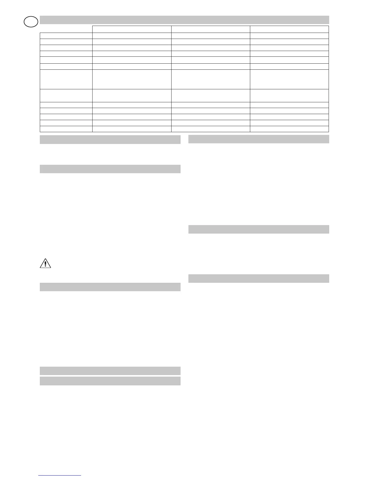
1. TECHNICAL DETAILS
GLOBE7 GLOBE7J GLOBE10
Power supply 230 V~
/ 50-60 Hz 120 V~ / 50-60Hz 230 V~ / 50-60 Hz
Absorption 0,7 A 1,4
A 1,2 A
Fuse F1 F1,6A F3,15A F1,6A
Thrust 500 N 500
N 900 N
Max stroke 2500 mm 2500
mm 2500 mm
Max load 7 m² 7
m² 10 m²
Opening speed 0,15 m/s
(chain)
0,18 m/s (belt)
0,15 m/s (chain)
0,18 m/s (belt)
0,12 m/s (belt + 71RC1)
0,15 m/s (chain)
0,18 m/s (belt)
Closing speed 0,10
m/s
(chain)
0,12 m/s (belt)
0,10 m/s (chain)
0,12 m/s (belt)
0,10 m/s (chain)
0,12 m/s (belt)
Service class 3 -
FREQUENT 3 - FREQUENT 3 - FREQUENT
Intermittence S2 =
30 min / S3= 50% S2 = 30 min / S3= 50% S2 = 30 min / S3= 50%
Temperature -20° C / +55° C -20° C / +55° C -20° C / +55° C
Degree of protection IP10 IP10 IP10
Control Panel 70R 70R 71R (71RC1)
2. REFERENCE ILLUSTRATIONS AND ACCESSORIES
The given operating and performance features can only be gua-
ranteed with the use of DITEC accessories and safety devices.
2.1 Standard installation references (fig. 1)
[1] Radio
[2] Drive unit
[3] Retention bracket
[4] Slide
[5] Release cord
[6] Guide
[7] Guide coupling
[8] Transmission
[9] Photocells
[10] Sensitive edge
[11] Transmitter support
[12] C
onnect the power supply to an omnipolar switch with contact opening
d
istance of at least 3 mm (not supplied by us) or by means of power plug.
Connection to supply mains must be carried out in an independent ra-
c
e
way separate from control connections and safety device connections.
2.2 Accessories
BATK1 Battery kit
GLOBEC Adapter for up and over doors with counterweights
ASB1 External release kit with cord and lock L=900 mm
ASB2
Cord release device L= 2000 mm
GLOBEL Extension set for 1
120 mm chain
GLOBELV Extension set for 1120 mm belt (for steel guide only)
GLOBEFM
Additional close stop
GLOBESI Intermediate support
GLOBEGF Iron track L=3000 mm
GLOBEGA Aluminium track L=3000 mm
3. INSTALLATION
3.1 Chain type GLOBE assembly (fig. 4)
- Extend the chain.
- Fit the coupling [1] as far as the guide stop. Fit the guide [2] as
far as the stop. Fit the coupling [3] as far as the guide stop [2].
- Superimpose the guide [4] on the coupling [3], correctly fit
the transmission in the guide [4]: lift the guide as shown in
the detail to permit fitting the transmission.
- Move the coupling [3] towards the transmission as far as
the guide stop [4].
Note:
the
guides must be fitted in a specific direction (see stops
[x] shown in illustration).
3.2 Belt type GLOBE assembly (fig.5)
- (fig. 5a) Fit the belt to the transmission and slide.
- (fig. 5b) Fit the belt stop as shown in the illustration.
- (fig. 5c) Fasten the two ends of the belt to the release pin
by means of the couplings keeping to the pin direction
shown in the illustration.
-
(fig. 5d) Fit the drive pin (belt - transmission - slide) in the guide.
- (fig. 5e) Pass the belt around the pulley and secure by
means of the pin [Y]. Fit the guide as shown in fig. 3, lock
in the drive unit as far as the stop and tighten screw [K].
-
(fig. 5f) Push the transmission towards the outside of the
guide and fasten the retention bracket to the wall.
3.3 Chain or belt tensioning (fig.6)
- Correct tensioning is achieved by leaving 1÷2 mm between
the spring retainer [E] and stop [H] to enable the spring [E]
to work in the best possible way.
Attention: over-tightening could affect proper operation of the
automatic system.
3.4 GLOBE installation (fig. 7-8)
- Establish and trace the retention point of the guide on the
wall and ceiling (fig. 7a).
Attention:
in the case of spring balanced up and over doors with
c
ounterweights use GLOBEC (fig. 7b). With the off-board drive
unit, fit the guide to the wall using the transmission bracket (fig. 7c).
(fig. 7d) Fit the bracket [3] and secure using the screws
provided. Lift the unit and bend the brackets to measure (if
necessary eliminate the excess parts), then fasten to the ceiling.
Attention: (fig. 8) to fully open sectional doors with special
heights, the arm [M] can be shortened and the coupling point
[L] can be moved from 20 mm to 100 mm further in than [G].
If necessary, fit a shim [J] (not supplied by us, max 200 mm)
between the wall and the tightener [L]. This way the stroke of the
slide will be increased by exploiting all the available guide.
- Manually
release (see OPERATING INSTRUCTIONS)
and move the slide up to the closed door, then fit the re-
tention bracket
[G] on the top edge, possibly interposing
the supplied reinforcing angular [P] (fig.8c-d); afterwards,
re-lock the slide by moving the door manually.
- (Fig.
9) Fit the stop in the guide and secure in the desired
opening position.
-
(Fig.
10) For stronger fastening the intermediate support
GLOBESI can be installed.
 Loading...